
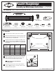
Product Manual

©2011 ALVIN & COMPANY, INC.
2
1101, 1102, and 2201 Assembly and Maintenance Instructions
6
7
8
9
10
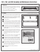
Assemble right rear wire connector as shown in Figure 3
and fasten to board. Select screw length based upon
board thickness.* Fasten screws securely. Rear pulleys (F)
are designed to be tight fitting and do not spin freely.
*For board thicknesses of 5/8" or less:
Use 5/8" screws (K) in place of 3/4" screws as shown
in Figures 3 and 4. Do not use 3/4" screws included
with hardware kit since they might break through
bottom of board.
Assemble left rear wire connector as shown in Figure 4
and fasten to board. Fasten screws securely. Rear pulleys
are designed to be tight fitting and do not spin freely.
Place straightedge in center of board parallel to front
edge as shown in Figure 5. Loop upper wires around
rear pulleys in rear wire connectors making sure that
spring is centered.
Thread lower left and lower right wires through front
wire connectors. Wire should pass between connector
and board as shown in Figure 6. With spring still
centered at top, pull slack out of wire passing through
lower left connector and wrap wire around mounting
screw. Fasten screw securely. Repeat on the right side,
using care to set spring tension as directed in Figure 5
for best performance.
Excess wire can be trimmed off but leave several
inches for future adjustment.
1
2
3
4
5
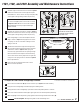
To Adjust & Lock Parallel Straightedge Position:
Be sure all three brake knobs (B, G) are free and loose. (See Figure 5 for brake locations.)
Grasp one end of straightedge and hold firmly against drawing board.
Gently pivot other end of straightedge up or down until desired parallel position is reached.
Secure wire under thumbscrew brake (G) in upper right corner to maintain parallel positioning.
With straightedge in desired position, gently tighten both left and right thumbscrew brakes (B).
CAUTION
Do not overtighten. Overtightening brake screws will damage wires.
Figure 4
* Use the 5/8" screws in place
of the 3/4" screws for boards
5/8" thick or less.
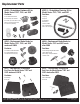
L
F
J
D
Figure 5
Stretch spring to 2½" in length
for proper tension
Center spring on board
Brake
Knob
B
Brake
Knob
B
D
E
C C
G
B
Figure 6
Figure 3
G
J
E
H
J
K
*
J K
or
*
L
F
or
C
J
Some features not available on 1102 model series.