
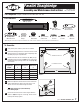
Product Manual

©2011 ALVIN & COMPANY, INC.
1
Parallel Straightedge
Assembly and Maintenance Instructions
For model series
1101, 1102, and 2201
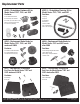
C 2pcs Front
Wire Connectors
E 1pc Right Rear
Wire Connector
D 1pc Left Rear
Wire Connector
F 2pcs Rear
Pulleys
G 1pc Rear
Brake Knob
H 1pc 1/2" Brake
Stud Screw
J 6pcs 3/4"
Screws*
K 2pcs 5/8"
Screws*
L 2pcs 3/8"
Washers
*NOTE: Only six screws total are required for installation. Two extra screws are included to accommodate various board thicknesses.
B 1pc Straightedge with Wire
A 1pc Spring
Tools Required: Phillips screwdriver and a drill with 1⁄16" bit
Parts Included:
To Assemble:
Verify that all parts shown in parts list are included.
Check that drawing board has a solid outer frame to hold
screws and that it is not warped. Alvin straightedges will
not work properly on warped boards.
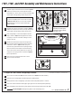
Position front and rear wire connectors (C, D, E) on top
of drawing board as shown in
Figure 1
. Use chart below
to determine proper spacing. Center the straightedge (B)
on the board.
Mark screw positions for front and rear wire connectors
and pre-drill pilot holes about 1/4" deep using a 1/16"
drill bit. Use care not to drill through the board.
TIP
Wrap masking tape 1/4" from drill tip
to set drilling depth.
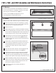
Fasten front wire connectors to front edge of board as
shown in Figure 2 using 3/4" screws (J). Fasten screws
half way. Do not fully tighten.
1
2
3
Figure 1
For
Straightedge
Length
Dimension
1
Dimension
2
Dimension
3
30" 27¾" 28¾" 3/4"
36" 33¾" 34¾" 3/4"
42" 39¾" 40¾" 3/4"
48" 45¾" 46¾" 3/4"
60" 57¾" 58¾" 3/4"
Figure 2
4
5
3 3
2
1
Rear Wire Connectors
Front Wire Connectors
D
C C
E
C
J
Some features not available on 1102 model series.