
user manual


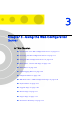
Table Of Contents
- Voice Gateways System Manual
- About This Manual
- Contents
- Chapter 1 - System Description
- Chapter 2 - Installation
- Chapter 3 - Using the Web Configuration Server
- 3.1 Introduction to the Web Configuration Server
- 3.2 Accessing the Web Configuration Server
- 3.3 Using the Web Configuration Server
- 3.4 Home Menu - Product Info Page
- 3.5 WAN Menu
- 3.6 VLAN Tagging Menu
- 3.7 Telephone Menu
- 3.8 BW Reservation - DRAP Configuration Page
- 3.9 System Menu
- 3.10 Upgrade Page
- 3.11 Restart Page
- 3.12 Logout Page
- 3.13 Parameters Summary
- Appendix A - Internal Class 5 Services
- Appendix B - Default Telephony Parameters
- Appendix C - New Features
- Glossary
10 Installation
Chapter 2 - Installation
For more details on configuration of DHCP and static IP parameters, refer to
Section 3.5.2.
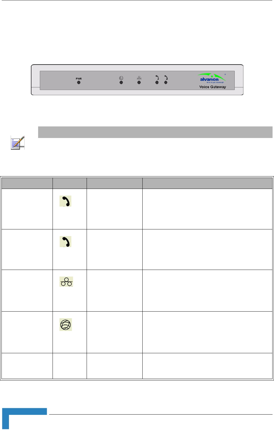
2.2.3 LEDs
Figure 2-2: VG-1D2V Front Panel
NOTE
The VG-1D1V has a single Phone LED.
Table 2-2: Voice Gateway LEDs
Name Symbol Description Functionality
Phone 1 Phone service
indication
Off -Phone line does not get IP telephony
services
On - Phone line is connected to the
IP-telephony system
Phone 2
(VG-1D2V only)
Phone service
indication
Off -Phone line does not get IP telephony
services
On - Phone line is connected to the
IP-telephony system
LAN LAN port status
indication
Off - Ethernet Link not detected
On - Ethernet link connected, no activity
Blinking - Ethernet link activity
WAN WAN port status
indication
Off - Ethernet link not detected
On - Ethernet link connected, no activity
Blinking - Ethernet link activity
POWER PWR Power Indication
Off - unit is not powered or power failed
Green - power OK