
Programming instructions

Installation
2-13
Alvarion
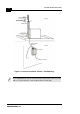
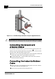
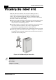
4. After connecting the outdoor unit to the indoor unit using the Indoor-
to-Outdoor cable, connect the power cord to the unit’s AC socket,
located on the bottom panel shown in Figure 2-6. Connect the other
end of the power cord to the AC mains after verifying that the unit is
rated for the voltage in the country of use; the AC rating is indicated
on the bottom panel of the Indoor unit.
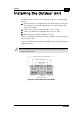
Figure 2-6: Indoor Unit Bottom Panel
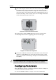
5.
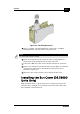
Verify that the yellow POWER LED located on the top panel is lit,
indicating that the unit is supplying power to the radio port.
Figure 2-7: Indoor Unit Top Panel
6.
Connect the 10BaseT connector to the network. The cable connection
should be straight Ethernet if connecting the Indoor unit to a Hub
and a crossed cable if connecting it directly to a PC Network Interface
Card (NIC).
Configuring Parameters
Before aligning the antenna, certain key parameters must be configured
to enable connectivity with linked units.
See “BreezeCONFIG DS Modes” on page 3-4 for more information.
NOTE:
The length of the Ethernet cable connecting the indoor unit to the user's equipment,
together with the length of the Indoor-to-Outdoor cable, should not exceed 90 meters.