BreezeACCESS® VL System Manual SW Version 5.
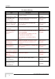
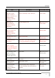
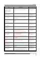
Legal Rights Doc um e nt H ist ory Topic FIPS 197 Description Version/Date Issued Optional support (under license) of FIPS 197 compliant encryption SW Version 4.0, AU/SU with 25dBi antennas for point-to-point links in the 4.9 GHz band SW Version 4.0, SW Version 4.0, Section: 1.2, 4.2.6.2.12 AUS can support up to 8 SU-3/SU-6 units (increased from 5) IDU-ODU Cable Update of maximum length of IDU-ODU cable SW Version 4.0, Sections: 4.2.5.7.3, 4.2.6.7 4.9 GHz B&B models Section: 1.4, 1.7.1, 1.7.5.
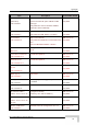
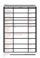
Legal Rights Topic Service Provider Link (VLAN QinQ) Section 4.2.6.4.1 Description Version/Date Issued New feature SW Version 4.0, Service Provider Link option added to VLAN Link Type. July 2006 New parameters: Service Provider VLAN ID, VLAN QinQ Protocol Ethertpe. MAC Address List Improved functionality. SW Version 4.0, Section 4.2.6.4.7 New parameter: MAC Address List Action July 2006 Concatenation Improved mechanism. SW Version 4.0, Section 4.2.6.5.
Legal Rights Topic Ethernet packet length Description Version/Date Issued Updated maximum length SW Version 4.0, Section 4.2.5.1.1 Basic Parameters Table July 2006 Updated according to applicable changes (new/removed parameters) SW Version 4.0, Updated according to applicable changes (new/removed parameters) SW Version 4.0, Updated according to applicable changes (new/removed parameters) SW Version 4.0, Updated according to applicable changes (new/removed parameters) SW Version 4.
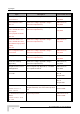
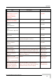
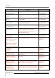
Legal Rights Topic Q in Q (Service Provider Link) improvements. Description Version/Date Issued Improved handling of management frames. Support of Ethertypes 9100, 9200 (hex). SW Version 4.0.27 Default changed to 8171 SW Version 4.0.27 October 2006 Sections 4.2.6.4.1.2, 4.2.6.4.1.3.4, 4.2.6.4.1.8, MIB (Appendix E), Parameters Summary (Appendix F) DRAP UDP Port Section 4.2.6.6.4.
Legal Rights Topic Description Version/Date Issued MIR Threshold Percent Sections 4.2.6.6.2, 4.2.6.6.2.9, Parameters Summary (Appendix E) New MIR/CIR parameter SW Version 4.5 June 2007 Station Allowed Option Section 4.2.6.4.7, 4.2.6.4.7.4, Parameters Summary (Appendix E) New feature SW Version 4.5 June 2007 Antenna Compliance Statement (in Legal Rights) New SW Version 4.5 June 2007 Transmit Power Compliance With Regulations Section 3.1.2 New SW Version 4.
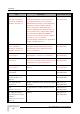
Legal Rights Topic Description Version/Date Issued Default value of DFS Minimum Pulses to Detect Section 4.2.6.2.4.3.6, Parameters Summary (Appendix E) 4 for FCC, 8 for other (ETSI) SW Version 4.5 July 2007 FCC Radiation Hazard Warning (in Legal Rights) Updated SW Version 4.5 July 2007 Usable frequencies limitations Section 4.2.6.2.4.2 Updated SW Version 4.5 July 2007 Re-apply Country Code Values Section 4.2.6.8.2, Appendix A New feature SW Version 4.5 July 2007 Basic Parameters Section 4.2.
Legal Rights Topic Correct Run-Time update of Air Interface Parameters Appendix E - Parameters Summary, Section E.1.3 Description Version/Date Issued Preferred AU MAC Address, Arbitration InterFrame Spacing, Wireless Trap Threshold are not updated in run-time (reset is required). SW Version 5.
Legal Rights Topic Description Version/Date Issued Maximum Number of Associations with Data Encryption enabled Sections 4.2.6.2.12, 4.2.6.7.2 Maximum Number of Associations must be set to 124 or lower to enable Data Encryption SW Version 5.0 November 2007 MIR and CIR Parameters Section 4.2.6.6.2 Updated description of Burst Duration algorithm SW Version 5.0 November 2007 RTS Threshold For HW Rev C and higher, the maximum is 4092 bytes. This is also the default for RTS Threshold in AU.
Legal Rights Topic Description Version/Date Issued Low Priority AIFS Section 4.2.6.6.3.5.2 The range has been changed from 3-254 to 350. SW Version 5.0 December 2007 MIR Defaults Table 4-12 Default value for SU-54 have been updated (53,888) SW Version 5.0 December 2007 Regulation Max EIRP Table 3-2 Updated (New Country Codes, updated values for UK 5.8 GHz) SW Version 5.0 December 2007 Scanning Mode Section 4.2.6.2.
Legal Rights Topic Description Version/Date Issued Show Spectrum Analysis Parameters & Data, Section 4.2.6.2.14.8 Updated manual SW Version 5.1 April 2008 Show Best AU Parameters and Data, Section 4.2.6.2.6.4 RSSI of the received signal has been added SW Version 5.1 April 2008 ATPC Delta from Minimum SNR Level, Section 4.2.6.2.8.3.3 Added default value for 0.9 GHz band SW Version 5.1 April 2008 MIR/CIR ranges and defaults, Table 4-12, Table 4-13 Added values for SU-8 SW Version 5.
Legal Rights Le ga l Right s © Copyright 2008 Alvarion Ltd. All rights reserved. The material contained herein is proprietary, privileged, and confidential and owned by Alvarion or its third party licensors. No disclosure thereof shall be made to third parties without the express written permission of Alvarion Ltd. Alvarion Ltd. reserves the right to alter the equipment specifications and descriptions in this publication without prior notice.
Legal Rights Bug fixes, temporary patches and/or workarounds may be supplied as Firmware updates. Additional hardware, if required, to install or use Firmware updates must be purchased by the Customer. Alvarion will be obligated to support solely the two (2) most recent Software major releases.
Legal Rights GENERATED. ALL OF WHICH ARE EXPRESSLY DISCLAIMED. ALVARION’ WARRANTIES HEREIN RUN ONLY TO PURCHASER, AND ARE NOT EXTENDED TO ANY THIRD PARTIES. ALVARION NEITHER ASSUMES NOR AUTHORIZES ANY OTHER PERSON TO ASSUME FOR IT ANY OTHER LIABILITY IN CONNECTION WITH THE SALE, INSTALLATION, MAINTENANCE OR USE OF ITS PRODUCTS.
Legal Rights and industrial environments. This equipment generates, uses, and can radiate radio frequency energy and, if not installed and used in accordance with the instruction manual, may cause harmful interference to radio communications. Operation of this equipment in a residential area is likely to cause harmful interference in which case the user will be required to correct the interference at the user’s own expense.
Legal Rights Out door U nit a nd Ant e nna I nst a lla t ion a nd Grounding Ensure that outdoor units, antennas and supporting structures are properly installed to eliminate any physical hazard to either people or property. Make sure that the installation of the outdoor unit, antenna and cables is performed in accordance with all relevant national and local building and safety codes.
Legal Rights BreezeACCESS VL System Manual xvii
Important Notice I m port a nt N ot ic e This user manual is delivered subject to the following conditions and restrictions: This manual contains proprietary information belonging to Alvarion Ltd. Such information is supplied solely for the purpose of assisting properly authorized users of the respective Alvarion products.
About T his M a nua l This manual describes the BreezeACCESS VL Broadband Wireless Access System Release 5.1 and how to install, operate and manage the system components. This manual is intended for technicians responsible for installing, setting up and operating the BreezeACCESS VL system, and for system administrators responsible for managing the system. This manual contains the following chapters and appendices: Chapter 1 – System description: Describes the BreezeAccess VL system and its components.
About This Manual Appendix F – Troubleshooting.
Cont e nt s Le ga l Right s............................................................................................x ii I m port a nt N ot ic e ................................................................................. x viii Cha pt e r 1 - Syst e m De sc ript ion ...............................................................1 1.1 Introducing BreezeACCESS VL................................................................................... 2 1.2 Base Station Equipment...........................
Contents 1.7.5 Physical and Electrical ....................................................................................... 22 1.7.6 Environmental .................................................................................................... 30 Cha pt e r 2 - I nst a lla t ion .......................................................................... 3 1 2.1 Installation Requirements ..........................................................................................32 2.1.1 Packing List...
Contents Cha pt e r 3 - Com m issioning ....................................................................6 7 3.1 Configuring Basic Parameters .................................................................................. 68 3.1.1 Initial Configuration ............................................................................................ 68 3.1.2 Country Code Selection..................................................................................... 70 3.1.
Contents Appe ndix A - Soft w a re V e rsion Loa ding U sing T FT P .......................... 2 0 5 Appe ndix B - File Dow nloa d a nd U ploa d U sing T FT P .......................... 2 0 9 Appe ndix C - U sing t he Se t Fa c t ory De fa ult s U t ilit y ........................... 2 1 3 Appe ndix D - Pre pa ring t he I ndoor t o Out door SU Ca ble .................... 2 1 5 Appe ndix E - Pa ra m e t e rs Sum m a ry ..................................................... 2 1 9 E.1 Parameters Summary ......
Figure s Figure 2-1: Threaded Holes/Grooves ......................................................................................................... 39 Figure 2-2: 3" Pole Installation Using Special Clamps................................................................................ 39 Figure 2-3: Back View of the new SU-A-ODU ............................................................................................
Figures Figure 4-1: Main Menu (Administrator Level) ..............................................................................................87 Figure 4-2: Ethernet Connector Pin Assignments .....................................................................................
T a ble s Table 1-1: Frequency Bands......................................................................................................................... 3 Table 1-2: AU Antennas................................................................................................................................ 5 Table 1-3: Subscriber Unit ODU Types ........................................................................................................ 8 Table 1-4: SU-A/E Subscriber Unit Types ...............
Tables Table 2-2: Approved Category 5E Ethernet Cables ....................................................................................35 Table 2-3: SU-I Panel Components.............................................................................................................52 Table 2-4: BS-PS LED Functionality ...........................................................................................................61 Table 3-1: Basic Parameters ....................................................
1 Chapter 1 - Syst e m De sc ript ion I n T his Cha pt e r: Introducing BreezeACCESS VL, page 2 Base Station Equipment, page 4 Subscriber Unit, page 7 BreezeACCESS VL B&B (4.
Chapter 1 - System Description 1 .1 I nt roduc ing Bre e ze ACCESS V L BreezeACCESS VL is a high capacity, IP services oriented Broadband Wireless Access system. The system employs wireless packet switched data technology to support high-speed IP services including fast Internet and Virtual Private Networks. BreezeACCESS VL users are provided with a network connection that is always on, supporting immediate access to the Internet and other IP services at high data rates.
Introducing BreezeACCESS VL Table 1-1: Frequency Bands Band Frequencies (MHz) 4.9 4900 – 5100 5.2 5150 – 5350 5.3 5250 – 5350 5.4 5470 – 5725 5.8 5725 – 5875 0.9 902 - 928 The available frequencies, as well as other parameters, depend on applicable local regulations. The actual operating frequencies used by the system can be configured according to applicable radio regulations and specific deployment considerations.
Chapter 1 - System Description 1 .2 Ba se St a t ion Equipm e nt The Access Units, installed at the Base Station site, provide all the functionality necessary to communicate with the Subscriber Units and to connect to the backbone of the Service Provider. There are 2 lines of Access Units with different architectures: Modular Base Station Equipment Standalone “Micro-Cell” Access Unit 1 .2 .
Base Station Equipment The AU-BS Access Unit can serve up to 512 Subscriber Units (124 when Data Encryption is used). The AUS-BS Access Unit can serve up to 8 SUs except SU-54 (refer to section 1.3 for details on availability of SU types in different bands). Optionally, it may be licensed to support also SU-54 units (in bands where SU-54 unit type is available). NOTE For convenience, all references to AU-BS are applicable also for AUS-BS, unless explicitly stated otherwise.
Chapter 1 - System Description traffic between the indoor module and the outdoor unit, and also transfers power (54 VDC) and control from the indoor module to the outdoor unit. 1 .2 .2 St a nda lone “M ic ro-c e ll” Ac c e ss U nit The standalone AU-E-SA Access Unit is very similar to the AU-E-BS unit.
Subscriber Unit 1 .3 Subsc ribe r U nit The Subscriber Unit (SU) installed at the customer premises enables the customer data connection to the Access Unit. The Subscriber Unit provides an efficient platform for high speed Internet and Intranet services. The use of packet switching technology provides the user with a connection to the network that is always on, enabling immediate access to services.
Chapter 1 - System Description Table 1-3: Subscriber Unit ODU Types SU Type Antenna Description SU-A-ODU Vertically polarized high-gain flat antenna integrated on the front panel. Not available in the 0.9 GHz band. New SU-A-ODU Vertically/horizontally polarized high-gain flat antenna integrated on the front panel. The smaller size new SU-A-ODU (HW revision E) is currently available only in the 5.4 GHz and 5.8 GHz bands. SU-E-ODU A connection to an external antenna (not included).
Subscriber Unit Table 1-4: SU-A/E Subscriber Unit Types SU Type Description SU-54-BD (SU-54) A high-rate CPE that supports a full LAN. Not available in the 900 MHz band. SU-6-BD (SU-6) A medium rate CPE that supports a full LAN*. Not available in the 900 MHz band. SU-3-BD (SU-3) An entry level CPE that supports a full LAN** SU-8-BD (SU-8) A medium rate CPE that supports a full LAN. Available only in the 900 MHz band.
Chapter 1 - System Description 1 .3 .2 SU -I Subsc ribe r U nit s The SU-I is a compact Subscriber Unit intended for indoor installations by a non-professional user.
BreezeACCESS VL B&B (4.9 GHz only) 1 .4 Bre e ze ACCESS V L B& B (4 .9 GH z only) BreezeACCESS VL B&B is available in the 4.9 GHz band to support point-topoint applications. A B&B point-to-point link includes: AU-D-SA-4.9-6-VL: A standalone AU with a 25 dBi, 6° high gain directional antenna. SU-D-4.9-54-BD-VL: SU-54-BD with a 25 dBi, 6° high gain directional antenna.
Chapter 1 - System Description 1 .5 N e t w ork ing Equipm e nt The Base Station equipment is connected to the backbone through standard data communication and telecommunication equipment. The 10/100BaseT ports of the AU modules can be connected directly to a multi-port router or to an Ethernet switch connected to a router. The point-to-point link from the Base Station to the backbone can be either wired or wireless. Data to the Internet is routed to the backbone through standard routers.
Management Systems 1 .6 M a na ge m e nt Syst e m s The end-to-end IP-based architecture of the system enables full management of all components, from any point in the system. BreezeACCESS VL components can be managed using standard management tools through SNMP agents that implement standard and proprietary MIBs for remote setting of operational modes and parameters. The same SNMP management tools can also be used to manage other system components including switches, routers and transmission equipment.
Chapter 1 - System Description (NOCs), providing the network Operation, Administration and Maintenance (OA&M) staff and managers with all the network surveillance, monitoring and configuration capabilities that they require in order to effectively manage the BWA network while keeping the resources and expenses at a minimum. AlvariSTAR is designed to offer the network’s OA&M staff with a unified, scalable and distributable network management system.
Management Systems AlvariSTAR provides the following BWA network management functionality: Device Discovery Device Inventory Topology Fault Management Configuration Management Data Collection Performance Monitoring Device embedded Software Upgrade Security Management Northbound interface to other Network Management Systems.
Chapter 1 - System Description 1 .7 Spe c ific a t ions 1 .7 .1 Ra dio Table 1-6: Radio Specifications Item Description Frequency1 0.9 GHz Family: 902 – 928 GHz 4.9 GHz Family: 4.900 – 5.100 GHz 5.2 GHz Family: 5.150 – 5.350 GHz 5.3 GHz Family: 5.250 – 5.350 GHz 5.4 GHz Family: 5.470 – 5.725 GHz 5.8 GHz Family: 5.725 – 5.875 GHz Operation Mode Time Division Duplex (TDD) Channel Bandwidth1 20 MHz 10 MHz (HW Revision C and higher) 5 MHz (0.
Specifications Table 1-6: Radio Specifications Item Description External Subscriber Antenna for SU-E 0.9 GHz 10.5 dBi minimum in the 902-928 MHz band. 55o AZ x 60o EL, vertical/horizontal polarization, RoHS compliant AU Antennas (optional) AU-Ant-5G-16-60: 16 dBi typical, 5.150-5.875 GHz, 60o AZ x 10o EL sector antenna, vertical polarization, compliant with ETSI EN 302 326-3 V1.2.1 (2007-01) AU-Ant-5G-17-90: 17 dBi typical, 5.150-5.
Chapter 1 - System Description Table 1-6: Radio Specifications Item Sensitivity, Minimum (dBm at antenna port, PER<10%, 20 MHz bandwidth3) Modulation Description Modulation Level4 Sensitivity (HW Rev. A) Sensitivity (HW Rev.
Specifications 1 .7 .2 Da t a Com m unic a t ion Table 1-7: Data Communication Item Description Standard compliance IEEE 802.3 CSMA/CD VLAN Support Based on IEEE 802.1Q Layer-2 Traffic Prioritization Based on IEEE 802.
Chapter 1 - System Description 1 .7 .
Specifications 1 .7 .4 St a nda rds Com plia nc e , Ge ne ra l Table 1-9: Standards Compliance, General Type EMC Standard FCC Part 15 class B ETSI EN 300 489-1 Safety UL 1950 EN 60950 Environmental Operation ETS 300 019 part 2-3 class 3.2E for indoor ETS 300 019 part 2-4 class 4.1E for outdoor Storage ETS 300 019-2-1 class 1.2E Transportation ETS 300 019-2-2 class 2.3 Lightning protection (AU-ODU Antenna connection) EN 61000-4-5, Class 3 (2kV) Radio FCC Part 15.
Chapter 1 - System Description 1 .7 .5 Physic a l a nd Ele c t ric a l 1.7.5.1 SU-A/E Subscriber Unit NOTE In the 5.4 and 5.8 GHz band, the equipment may be shipped with a new, smaller size SU-A-ODU that supports both horizontal and vertical polarization. 1 .7 .5 .1 .
Specifications 1 .7 .5 .1 .2 Conne c t ors Table 1-11: Connectors, SU-A/E Subscriber Unit Unit Connector IDU Description ETHERNET 10/100BaseT Ethernet (RJ-45) Cable connection to a PC: crossed Cable connection to a hub: straight RADIO 10/100BaseT Ethernet (RJ-45) AC IN 3 pin AC power plug SU-A-ODU INDOOR 10/100BaseT Ethernet (RJ-45), protected by a waterproof sealing assembly New SU-A-ODU (5.4/5.
Chapter 1 - System Description 1.7.5.2 SU-I Subscriber Unit 1 .7 .5 .2 .1 M e c ha nic a l a nd Ele c t ric a l Table 1-13: Mechanical and Electrical Specifications, SU-I Subscriber Unit Item Details Dimensions (cm) 11.8 (H) x 20 (L) x 3.1 (W) Weight (g) 600 Power Consumption 15W maximum DC Power Input (from Power Supply) 48 VDC Mains Power Input (to Power Supply) 90-265 VAC, 47-63 Hz 1 .7 .5 .2 .
Specifications 1.7.5.3 Modular Base Station Equipment 1 .7 .5 .3 .1 M e c ha nic a l Table 1-15: Mechanical Specifications, Modular Base Station Equipment Unit Structure Dimensions (cm) Weight (kg) BS-SH 19" rack (3U) or desktop 13 x 48.2 x 25.6 4.76 BS-PS-DC DC power supply module 12.9 x 7.0 x 25.3 1.2 BS-PS-AC AC power supply module 12.9 x 7.0 x 25.3 1.2 BS-AU Indoor module of the AU-BS access unit 12.9 x 3.5 x 25.5 0.15 AU-ODU pole or wall mountable 30.5 x 11.7 x 5.7 1.
Chapter 1 - System Description 1 .7 .5 .3 .2 Conne c t ors Table 1-16: Connectors, Modular Base Station Equipment Unit Connector BS-AU Description 10/100 BaseT 10/100BaseT Ethernet (RJ-45) with 2 embedded LEDs.
Specifications 1.7.5.4 Standalone Access Unit 1 .7 .5 .4 .1 M e c ha nic a l Table 1-18: Mechanical Specifications, Stand Alone Access Unit Unit Structure Dimensions (cm) Weight (kg) General An IDU indoor unit and an AUODU outdoor unit connected to a detached antenna IDU PS1073 Plastic box (black), desktop or wall mountable 14 x 6.6 x 3.5 0.3 AU-ODU Poll or wall mountable 30.5 x 11.7 x 5.7 1.8 AU-Ant-5G-16-60 2"-3.5" pole mountable 43.6 x 25 x 1.0 2.2 AU-Ant-5G-17-90 2"-3.
Chapter 1 - System Description 1 .7 .5 .4 .2 Conne c t ors Table 1-19: Connectors, Stand Alone Access Unit Unit Connector IDU Description ETHERNET 10/100BaseT Ethernet (RJ-45) Cable connection to a PC: crossed Cable connection to a hub: straight RADIO 10/100BaseT Ethernet (RJ-45) AC IN 3-PIN AC power plug INDOOR 10/100BaseT Ethernet (RJ-45), protected by a waterproof sealing assembly ANT N-Type jack, 50 ohm, lightning protected Antenna RF N-Type jack (on a 1.5m cable in the Omni-8-5.
Specifications 1.7.5.5 25dBi Antenna (for B&B point-to-point link) Table 1-21: 25dBi Antenna Specifications Item Description Regulatory Compliance ETSI EN 302 085 V1.1.2 (2001-02) Range1 Frequency Range 4.900-5.100 GHz Gain 25dBi min. Azimuth Beamwidth 6° Elevation Beamwidth 6° Polarization Linear (Vertical/Horizontal) Dimensions (cm) 45 x 45 x 3 Weight (kg) 3 (max, excluding mounting kit) Connector N-Type, Female Mounting Kit 2.75”-3.5” pole, 0 to -10° tilt, 2.2kg 1.7.5.
Chapter 1 - System Description 1 .7 .
2 Chapter 2 - I nst a llat ion I n T his Cha pt e r: Installation Requirements, page 32 Equipment Positioning Guidelines, page 36 Installing the Outdoor Unit, page 38 Installing the Universal IDU Indoor Unit, page 49 Installing the SU-I, page 51
Chapter 2 - Installation 2 .1 I nst a lla t ion Re quire m e nt s This section describes all the supplies required to install the BreezeACCESS VL system components and the items included in each installation package. NOTE Installation requirements for SU-I are provided in section 2.5 on page 51. 2 .1 .1 Pa c k ing List 2.1.1.
Installation Requirements Pole mounting kit for the ODU (the kit for the new, smaller-size ODU is different from the kit for all other ODUs) An IDU to ODU cable kit, including 20m Category 5E Ethernet cable with a shielded RJ-45 connector crimped on one end, a waterproof sealing assembly and two shielded RJ-45 connectors (not applicable for the new smaller size SU-A-ODU and SU-E-ODU). 2.1.1.
Chapter 2 - Installation BS-PS-DC power supply module DC power cable 2.1.1.3 AU-E-SA Standalone Access Unit The AU-E-SA installation kit includes the following components: IDU indoor unit with a wall mounting kit Mains power cord AU-ODU outdoor unit Pole mounting kit for the AU-ODU RF cable 2.1.1.
Installation Requirements Portable PC with Ethernet card and Telnet software or AlvariCRAFT for BreezeACCESS VL* application and a crossed Ethernet cable Installation tools and materials, including appropriate means (e.g. a pole) for installing the outdoor unit. 2 .1 .2 I ndoor-t o-Out door Ca ble s NOTE The length of the indoor-to-outdoor Ethernet cable should not exceed 90 meters.
Chapter 2 - Installation 2 .2 Equipm e nt Posit ioning Guide line s This section provides key guidelines for selecting the optimal installation locations for the various BreezeACCESS VL system components. CAUTION ONLY experienced installation professionals who are familiar with local building and safety codes and, wherever applicable, are licensed by the appropriate government regulatory authorities should install outdoor units and antennas.
Equipment Positioning Guidelines The indoor equipment should be installed as close as possible to the location where the indoor-to-outdoor cable enters the building. The location of the indoor equipment should take into account its connection to a power outlet and the customer’s equipment.
Chapter 2 - Installation 2 .3 I nst a lling t he Out door U nit The following sections describe how to install the outdoor units, including pole mounting the ODU, and connecting the indoor-to-outdoor, grounding and RF cables. NOTE Ensure that outdoor units, antennas and supporting structures are properly installed to eliminate any physical hazard to either people or property.
Installing the Outdoor Unit Figure 2-1: Threaded Holes/Grooves Figure 2-2 illustrates the method of mounting an outdoor unit on a pole, using the clamps and threaded rods. Figure 2-2: 3" Pole Installation Using Special Clamps NOTE There is a groove on one end of the threaded rod. Be sure to insert the threaded rods with the grooves pointing outward, as these grooves enable you to use a screwdriver to fasten the rods to the unit.
Chapter 2 - Installation 2 .3 .2 Pole M ount ing t he N e w SU -A/E-ODU The new SU-A/E-ODU can be mounted on a 1" to 4" pole using one of the following options: A pole mounting kit is supplied with each unit. The kit includes a special clamp and a pair of threaded rods, flat washers, spring washers and nuts. There are two pairs of threaded holes on the back of the unit, enabling to use the mounting kit for installing the unit using either vertical or horizontal polarization.
Installing the Outdoor Unit For vertical polarization install the unit with the Polarization Arrow pointing upward (as in the figure above). For horizontal polarization install the unit with the Polarization Arrow pointing sideward and the connectors facing downward. 2.3.2.2 Pole Mounting the ODU Using the Clamp Figure 2-4 and Figure 2-5 illustrate how to mount an ODU on a pole, using the clamp and threaded rods. NOTE There is a groove on one end of the threaded rod.
Chapter 2 - Installation Figure 2-5: New SU-A-ODU Pole Installation Using the Special Clamp, Horizontal Polarization 42 BreezeACCESS VL System Manual
Installing the Outdoor Unit 2.3.2.3 Pole Mounting the ODU with the Tilt Accessory Figure 2-6: New SU-A-ODU Pole Installation Using the Tilt Accessory, Vertical Polarization To mount the ODU on a pole using the Tilt accessory: 1 Attach the Tilt accessory to the ODU using the two pairs of flat washers, spring washers and nuts supplied in the Tilt kit. 2 Mount the Tilt accessory on a 1" to 4" pole using two 9/16" metal bands.
Chapter 2 - Installation 2 .3 .3 Prot e c t ing ODU Conne c t ions Use appropriate sealing material to protect the connection against moisture and humidity. Use removable sealing material, such as a tar seal, to enable future access to the connector. NOTE ® Use high quality sealing material such as Scotch 130C Linerless Rubber Splicing Tape from 3M to ensure IP-67 compliant protection against dust and water.
Installing the Outdoor Unit Figure 2-7: Bottom Panel of the ODU (all ODUs except to new SU-A/E-ODU, shown without the sealing assembly) Figure 2-8: Bottom Panel of the New SU-A-ODU (without IDU COM Sealing Cap) Figure 2-9: Bottom Panel of the New SU-E-ODU-0.9 GHz (without the IDU COM Sealing Cap) NOTE The MAC Address of the unit is marked on both the ODU and the indoor unit (on the print side of the BS-AU module or on the bottom side of the Universal IDU).
Chapter 2 - Installation 2 .3 .5 Conne c t ing t he I ndoor-t o-Out door Ca ble 2.3.5.1 Units with an Installed Waterproof Seal (not applicable to new SU-A/E-ODU) To connect the indoor-to-outdoor cable: 1 Remove the two screws holding the waterproof seal to the outdoor unit and remove the waterproof seal. 2 Unscrew the top nut from the waterproof seal. Figure 2-10: The Waterproof Seal 3 Route a straight Category 5E Ethernet cable (8-wire, 24 AWG) through both the top nut and the waterproof seal.
Installing the Outdoor Unit 2.3.5.2 Units with a Waterproof Seal Supplied with the Ethernet Cable (not applicable to new SU-A/E-ODU) To connect the indoor-to-outdoor cable: 2.3.5.3 1 Verify that the o-ring supplied with the cable kit is in place. 2 Connect the RJ-45 connector of the Ethernet cable to the outdoor unit. 3 Attach the waterproof seal to the unit. Tighten the top nut. 4 Route the cable to the location selected for the indoor equipment.
Chapter 2 - Installation 5 48 Assemble a shielded RJ-45 connector with a protective cover on the indoor end of the IDU-ODU cable. See Appendix D for instructions on preparing the cable.
Installing the Universal IDU Indoor Unit 2 .4 I nst a lling t he U nive rsa l I DU I ndoor U nit The unit can be placed on a desktop or a shelf. Alternatively, it may be wall-mounted using the kit supplied with the unit. Figure 2-13: IDU PS 1073 Front Panel The RADIO connector and RESET button are located on the front panel, the ETHERNET connector is located on the side panel and LEDs are located on the top panel. CAUTION Do not connect the data equipment to the RADIO port.
Chapter 2 - Installation NOTE The length of the Ethernet cable connecting the indoor unit to the user's equipment, together with the length of the Indoor-to-Outdoor cable, should not exceed 100 meters. 2 .4 .1 RESET But t on Func t iona lit y Using a sharp object, press the recessed RESET button for a short time to reset the unit and reboot from the Main version. In units with ODU HW revision C and an IDU PS 1073, the RESET button can be used for setting the unit to its factory defaults.
Installing the SU-I 2 .5 I nst a lling t he SU -I The following sections describe how to install the SU-I CPE. 2 .5 .1 I nst a lla t ion Re quire m e nt s 2.5.1.1 Packing List SU-I CPE Power Adapter 3 meters Ethernet Cable Wall/window mountable detached antenna kit, including wall/window mounting accessories and a 2 meters SMA-SMA (M/M) RF cable (only with SU-I-D). 2.5.1.
Chapter 2 - Installation 2 .5 .2 SU -I Conne c t ors a nd LEDs Figure 2-14: SU-I Panel Table 2-3: SU-I Panel Components Name Status Description Self-test and power indication Functionality Green: Power is available and self-test passed. Blinking Amber: Testing (not ready for operation) Red: Self-test failed.
Installing the SU-I Name Description SNR bar Received signal strength Indication Functionality Red LED: Signal is too low (SNR < 4dB). 8 green LEDs: Quality of the received signal. Orange LED: Signal is too high (SNR > 50dB).
Chapter 2 - Installation 3 Connect the RF cable supplied with the antenna to the SMA jack located on the unit’s front panel. Install the antenna using the instructions provided in Section 2.5.5 on page 54, and connect to it the other end of the RF cable. Do not over-tighten the SMA connectors. 4 If parameters are not pre-configured, configure the basic parameters as described in Section 3.1. 5 Align the antenna as described in Section 3.3.
Installing the SU-I NOTE Ensure that the antenna is mounted vertical to the floor, with the connector facing downward, and the front of the antenna facing to the exterior of the building, preferably directed towards the Base Station. CAUTION In order to avoid damage from lightning strikes, the antenna must be placed below roof level. 2.5.5.1 Wall Mount The installation kit includes 2 plastic anchors and 2 #8 screws. 1 2 If anchors are needed (wall-board, plaster board, etc.
Chapter 2 - Installation Figure 2-15: Wall Mounting the Antenna 2.5.5.2 Wall Mount with Rotation Capability The installation kit includes 4 L-type mounting plates (one top, one bottom, one Wall-V and one Wall-H), 6 M5 screws (with washers and spring washers), 2 plastic anchors and 2 #8 screws. 1 If anchors are needed (wall-board, plaster board, etc.), drill two holes (361 mm apart) for the anchors using a 5 mm drill bit and insert anchors.
Installing the SU-I 4 Attach the assembled plates to the flat rear-side of the antenna. Use the two remaining M5 screws to fasten them. 5 Fasten the antenna to the wall. Use the two #8 screws provided with the kit. Do not over tighten. 6 Connect the antenna cable to the connector located on the bottom side of the antenna. Use only the torque key supplied with the antenna. Do not over tighten. Do not use a wrench or a similar tightening tool.
Chapter 2 - Installation 2.5.5.3 Window Mount The installation kit includes 2 suction cups. 1 2 Attach the suction cups to the antenna. Refer to Figure 2-17 for directions. Determine the location of the antenna on the glass. Attach it to the window by pressing the suction cups onto the glass. 3 Connect the antenna cable to the connector located on the bottom side of the antenna. Use only the torque key supplied with the antenna. Do not over tighten. Do not use a wrench or a similar tightening tool.
Installing the SU-I 2.5.5.4 Window Mount with Rotation Capability The installation kit includes the following: 4 PHK40*16PT screws (1), 2 M4 washers (2), 2 rotation bars (3) and 2 suction cups (4). 1 Attach the rotation bars to the antenna and the suction cups to the rotation bars. Refer to Figure 2-18 for directions. 2 Determine the location of the antenna on the glass. Attach it to the window by pressing the suction cups onto the glass.
Chapter 2 - Installation 2 .6 I nst a lling t he M odula r Ba se St a t ion Equipm e nt The following sections describe the slot assignment for the Base Station chassis, provide illustrated descriptions of the power supply modules and Access Unit network interface modules, and describe how to install the Base Station equipment. 2 .6 .1 BS-SH Slot Assignm e nt The Base Station chassis comprises ten slots, as shown in Figure 2-19.
Installing the Modular Base Station Equipment 2 .6 .2 BS-PS-AC Pow e r Supply M odule The BS-PS-AC is an AC to DC converter that provides power to all the BS-AU modules installed in the BS-SH chassis. Figure 2-20 shows the BS-PS-AC front panel. Figure 2-20: BS-PS-AC Front Panel The BS-PS-AC includes a power input connector, marked AC IN, for connecting the AC power cord to the mains. The ON/OFF Power Switch controls the flow of mains power to the power supply module.
Chapter 2 - Installation 2 .6 .3 BS-PS-DC Pow e r Supply M odule The BS-PS-DC is a DC-to-DC converter that provides power to all the BS-AU modules installed in the BS-SH chassis. Figure 2-21 shows the BS-PS-DC front panel. Figure 2-21: BS-PS-DC Front Panel The BS-PS-DC provides a power input connector, marked -48VDC, for connecting the -48 VDC power source to the module.
Installing the Modular Base Station Equipment 2 .6 .4 BS-AU N e t w ork I nt e rfa c e M odule Figure 2-22 shows the front panel of the BS-AU Access Unit Network Interface module. Figure 2-22: BS-AU Front Panel The BS-AU provides the following interfaces: 10/100 BaseT: A 10/100BaseT Ethernet connector for connecting the BS-AU to the network. A straight Ethernet cable should be used to connect the module to a hub, router or switch.
Chapter 2 - Installation 2 .6 .5 I nst a lling t he BS-SH Cha ssis a nd M odule s This section describes how to install the power supply and Access Unit network interface modules in the Base Station chassis. To install the BS SH chassis and modules: 1 Install the BS-SH chassis in a 19” cabinet. To prevent over-heating, leave a free space of at least 1U between the upper/lower covers of the BS-SH chassis and other units in the cabinet. OR Place the BS-SH chassis on an appropriate shelf or table.
Installing the Modular Base Station Equipment OVERTEMP alarm indicator is off. Refer to Table 2-4 for a description of these LEDs. 11 Configure the basic parameters in all BS-AU modules as described in section 3.1. 12 Connect the 10/100 BaseT LAN connector(s) to the network. The cable connection should be straight Ethernet if connecting the indoor unit to a hub/switch and a crossed cable if connecting it directly to a PC Network Interface Card (NIC).
3 Chapter 3 - Com m issioning About T his Cha pt e r: Configuring Basic Parameters, page 68 Using the Optional Y-cable (New SU-A/E-ODU), page 73 Aligning the Subscriber Unit Antenna, page 74 Configuring the Subscriber Unit’s Maximum Modulation Level, page 76 Operation Verification, page 78
Chapter 3 - Commissioning 3 .1 Configuring Ba sic Pa ra m e t e rs 3 .1 .1 I nit ia l Configura t ion After completing the installation process, as described in the preceding chapter, the basic parameters must be configured to ensure that the unit operates correctly. After the basic parameters have been configured, additional parameters can be remotely configured via the Ethernet port or the wireless link using Telnet or SNMP management, or by loading a configuration file. Refer to section 4.
Configuring Basic Parameters Table 3-1: Basic Parameters Parameter Default Value Comment User Defined Frequency Subsets (SU) All frequencies Transmit Power Dependent on HW revision, unit type and Sub-Band Transmit Power in SU cannot be higher than the Maximum Tx Power parameter. Maximum Tx Power (SU) Dependent on HW revision and Sub-Band Maximum Tx Power cannot be higher than the upper limit according to the SubBand in use.
Chapter 3 - Commissioning Table 3-1: Basic Parameters Parameter Default Value VLAN ID-Management 65535 Authentication Algorithm Open System Data Encryption Option Disable Security Mode WEP Default Multicast Key (AU) Key 1 Promiscuous Authentication (AU) Disable Default Key (SU) Key 1 Key 1 to Key 4 00……0 (32 zeros, meaning no key) Comment Availability of security parameters depends on support according to the country code.
Configuring Basic Parameters 3 .1 .3 T ra nsm it Pow e r Com plia nc e Wit h Re gula t ions CAUTION In regions where local radio regulations limit the maximum transmit power of the unit the installer is responsible to properly set the Antenna Gain parameter (if configurable) according to the actual antenna being used. This will limit the upper limits of the Tx Power parameter in the AU and the Maximum Tx Power in the SU (where applicable) to the value of “Permitted EIRP-Antenna Gain”.
Chapter 3 - Commissioning 1. When operating at 4945 MHz, the Transmit Power parameter in the AU should not be set to a value above 11 dBm. The Maximum Transmit Power of the SU should not be set to a value above 10 dBm. 2. When operating at 5055 MHz, the Transmit Power parameter in the AU should not be set to a value above 13 dBm. The Maximum Transmit power of the SU should not be set to a value above 10 dBm.
Using the Optional Y-cable (New SU-A/E-ODU) 3 .2 U sing t he Opt iona l Y -c a ble (N e w SU -A/E-ODU ) A special Y-cable, available from Alvarion, enables to connect a a portable PC directly to the IDU COM port of the SU-A/E-ODU. This enables the installer to perform the entire process of configuring basic parameters, aligning the antenna and verifying proper operation of the unit right after completing the installation, minimizing the number of times the installer must climb to the roof.
Chapter 3 - Commissioning 3 .3 Aligning t he Subsc ribe r U nit Ant e nna NOTE This antenna alignment process described in this section is applicable to both the SU-A-ODU and the SU-I antenna, unless stated otherwise. The SNR bar display is located on the bottom panel of the SU-A-ODU/front panel of the SU-I indoor unit. The ten LEDs indicate the quality of the received signal. The higher the number of green LEDs indicating On, the higher the quality of the received signal.
Aligning the Subscriber Unit Antenna NOTE In some cases, the antenna may need to be tilted to ensure that the level at which the SU receives transmissions from the AU (and vice versa) is not too high. As a rule of thumb, if the SU is located at a distance of less than 300 meters from the AU, it is recommended to up-tilt the antenna by approximately 10° to 15°. To guarantee a safety margin from the saturation level (received signal of –40 dBm at the antenna port), the SNR should not be higher than 50 dB.
Chapter 3 - Commissioning 3 .4 Configuring t he Subsc ribe r U nit ’s M a x im um M odula t ion Le ve l This section describes how to configure the maximum modulation level for Subscriber Units. NOTE If the unit is associated with the AU, then the final configuration of the Maximum Modulation Level parameter may be performed remotely, for example, from the site of the AU or from another site.
Configuring the Subscriber Unit’s Maximum Modulation Level Table 3-3: Recommended Maximum Modulation Level* SNR Maximum Modulation Level SNR > 23 dB 8 21 dB < SNR < 23 dB 7 16 dB < SNR < 21 dB 6 13 dB < SNR < 16 dB 5 10 dB < SNR < 13 dB 4 8 dB < SNR < 10 dB 3 7 dB < SNR < 8 dB 2 6 dB < SNR < 7 dB 1 * The maximum supported value depends on the unit’s HW revision and on the Max Modulation Level according to the Sub-Band.
Chapter 3 - Commissioning 3 .5 Ope ra t ion V e rific a t ion The following sections describe how to verify the correct functioning of the Outdoor Unit, Indoor Unit, Ethernet connection and data connectivity. 3 .5 .1 Out door U nit V e rific a t ion To verify the correct operation of the Outdoor Unit, examine the LED indicators located on the bottom panel of the outdoor unit. The following tables list the provided LEDs and their associated indications.
Operation Verification Table 3-5: SU-ODU LEDs Name W-LINK Description Wireless Link Indictor Functionality Green – Unit is associated with an AU, no wireless link activity Blinking Green – Data received or transmitted on the wireless link. Blinking rate is proportional to wireless traffic rate Off – Wireless link is disabled Status Self-test and power indication Green – Power is available and self-test passed.
Chapter 3 - Commissioning Table 3-6: SU-ODU SNR Bar LED Functionality SNR Bar LEDs 80 SNR (typical) LED 1 (red) is On Signal is too low (SNR < 4 dB) LED 2 (green) is On SNR > 4 dB LEDs 2 to 3 (green) are On SNR > 8 dB LEDs 2 to 4 (green) are On SNR > 13 dB LEDs 2 to 5 (green) are On SNR > 19 dB LEDs 2 to 6 (green) are On SNR > 26 dB LEDs 2 to 7 (green) are On SNR > 31 dB LEDs 2 to 8 (green) are On SNR > 38 dB LEDs 2 to 9 (green) are On SNR > 44 dB LEDs 2 to 9 (green) and 10 (orange) ar
Operation Verification 3 .5 .2 I ndoor U nit V e rific a t ion To verify the correct operation of the indoor equipment, examine the LED indicators located on the top panel of the SU IDU and AU IDU units, or on the front panel of the BS-AU module. Table 3-7 provides information for the BS-AU IDU LEDs. Table 3-8 lists the LEDs of the PS1073 IDU. Table 3-7: BS-AU LEDs Name W-LINK Description Wireless link activity Functionality Green - At least one SU is associated. Blinking Red - No SU is associated.
Chapter 3 - Commissioning Table 3-8: PS1073 SU IDU / AU-SA IDU LEDs Name POWER Description Power Indication Functionality Green – IDU power is OK Off – No power or power failure ETH Self test and end-toend Ethernet connectivity Off – No Ethernet connectivity has been detected between the outdoor unit and the device connected to the indoor unit. Green – Self-test passed and Ethernet connection confirmed by the outdoor unit (Ethernet integrity check passed). 3 .5 .
Operation Verification Table 3-9: SU-I LEDs Name Description Self-test and power indication Status Functionality Green: Power is available and self-test passed. Blinking Amber: Testing (not ready for operation) Red: Self-test failed. Fatal error Ethernet activity/ connectivity indication Green: Ethernet link between the SU-I and the data equipment is detected, no activity Blinking Green: Ethernet connectivity is OK, with traffic on the port. Blinking rate proportional to traffic rate.
Chapter 3 - Commissioning Table 3-10: SU-I SNR Bar LED Functionality SNR Bar LEDs 3 .5 .
4 Chapter 4 - Ope rat ion a nd Adm inist rat ion I n T his Cha pt e r: Working with the Monitor Program, page 86 Menus and Parameters, page 89
Chapter 4 - Operation and Administration 4 .1 Work ing w it h t he M onit or Progra m 4 .1 .1 Ac c e ssing t he M onit or Progra m U sing T e lne t 1 Connect a PC to the Ethernet port, using a crossed cable. 2 Configure the PC's IP parameters to enable connectivity with the unit. The default IP address is 10.0.0.1. 3 Run the Telnet program. The Select Access Level menu is displayed. 4 Select the required access level, depending on your specific access rights.
Working with the Monitor Program BreezeACCESS VL// Official Release Version – Release Date: Main Menu ========== 1 – Info Screens 2 – Unit Control 3 - Basic Configuration 4 – Site Survey 5 - Advanced Configuration x - Exit >>> Figure 4-1: Main Menu (Administrator Level) NOTE If the Telnet session is not terminated properly; for example, if you simply close the window, the monitor program is blocked for several minutes.
Chapter 4 - Operation and Administration NOTE The program is automatically terminated following a determined period of inactivity. The default time out is 5 minutes and is configured with the Log Out Timer parameter. In some cases, to activate any configuration changes, you must reset the unit. Certain settings are automatically activated without having to reset the unit.
Menus and Parameters 4 .2 M e nus a nd Pa ra m e t e rs The following sections describe the menus and parameters provided by the Monitor program. 4 .2 .1 M a in M e nu The Main Menu enables to access the following menus, depending on your access level, as described in section 4.1. Info Screens: Provides a read only display of current parameter values. Available at all access levels.
Chapter 4 - Operation and Administration Show Advanced Configuration Show Country Dependent Parameters Show All Parameters 4.2.2.1 Show Unit Status The Show Unit Status menu is a read only menu that displays the current values of the following parameters: Unit Name: As defined in the Unit Control menu. Unit Type: Identifies the unit's function. Unit MAC Address: The unit's unique IEEE MAC address. Current Number of Associations (AU only): The total number of SUs associated with this AU.
Menus and Parameters SCANNING: The SU is searching for an AU with which to associate. If DFS is enabled and the SU is currently looking for its previous AU, the AU’s MAC Address will be displayed. ASSOCIATED: The SU is associated with an AU. AU MAC Address (SU only): The MAC address of the AU with which the unit is currently associated. If the unit is not associated with any AU, the address defaults to the IEEE broadcast address, which is FF-FF-FF-FF-FF-FF.
Chapter 4 - Operation and Administration FTP Parameters: General FTP parameters (common to SW Version Download, Configuration File Upload/Download and Event File Upload using FTP): FTP Server IP Address FTP Gateway IP Address FTP User Name FTP Password FTP Software Download Parameters: The parameters for SW download using FTP, as defined in Unit Control menu.
Menus and Parameters SU-54 Support (AUS only): Supported or Not Supported. Indicates whether the AUS can support SU-54 units (support of SU-54 units by AUS is a licensed feature available for all AUS units except AUS operating in the 0.9 GHz band). Wireless Link Prioritization Support (AU only): Supported or Not Supported. Indicates whether the unit supports the Wireless Link Prioritization feature (Wireless Link Prioritization is a licensed feature). 4.2.2.
Chapter 4 - Operation and Administration Allowed Bandwidth: If more than one bandwidth is allowed, then each bandwidth is associated with a different sub-band, as the bandwidth may affect the available frequencies. Regulation Max Tx Power at Antenna Port: The maximum transmit power allowed at the antenna port of the unit. Regulation Max EIRP: The maximum allowed EIRP (Effective Isotropic Radiated Power) in dBm, or No Limit. Min Modulation Level: The lowest allowed modulation level.
Menus and Parameters Change Unit Name Change Password Flash Memory Control Log Out Timer Ethernet Negotiation Mode Change System Location Event Log Menu Feature Upgrade SW Version Download Configuration File Upload/Download 4.2.3.1 Reset Unit The Reset Unit option enables resetting the unit. After reset, any modifications made to the system parameters are applied. 4.2.3.
Chapter 4 - Operation and Administration B Operator Defaults: Operator Defaults configuration can be defined by the Administrator using the Save Current Configuration As Operator Defaults option in this menu. It may also be defined at the factory according to specific operator's definition. The default Operator Defaults configuration is the Factory Defaults configuration. The current configuration file and the Operator Defaults configuration file can be uploaded/downloaded by the unit using FTP.
Menus and Parameters Table 4-2: Parameters not changed after Set Complete Factory/Operator Defaults Parameters Group Unit Control Parameters Parameter All Passwords FTP Server IP address* (see note below) FTP Gateway IP address* (see note below) FTP User Name* (see note below) FTP Password* (see note below) Ethernet Port Negotiation Mode Air Interface Parameters Selected Sub-Band (AU) Frequency (AU) DFS Required by Regulations (AU) Frequency Subset (AU) Antenna Gain (AU) Country Code Parameters Select
Chapter 4 - Operation and Administration Table 4-3: Parameters that are not changed after Set Partial Factory/Operator Defaults Parameters Group Parameter FTP Gateway IP Address FTP User Name FTP Password IP Parameters IP Address Subnet Mask Default Gateway Address DHCP Option Access to DHCP Security Parameters Authentication Algorithm Default Key (SU) Data Encryption Mode Default Multicast Key (AU) Security Mode Key # 1 to Key # 4 BreezeACCESS VL System Manual 98
Menus and Parameters Table 4-3: Parameters that are not changed after Set Partial Factory/Operator Defaults Parameters Group Air Interface Parameters Parameter ESSID Operator ESSID Option (AU) Operator ESSID (AU) Cell Distance Mode (AU) Maximum Cell Distance (AU) Per SU Distance Learning Option (AU) Selected Sub-Band (AU) Frequency (AU) DFS Required by Regulations (AU) SU Waiting Option (AU) Channel Reuse Option (AU) Radar Activity Assessment Period (AU) Maximum Number of Detections in Assessment Period (
Chapter 4 - Operation and Administration Table 4-3: Parameters that are not changed after Set Partial Factory/Operator Defaults Parameters Group Parameter Network Management Parameters Wi2 IP Address (SU) Performance Parameters Adaptive Modulation Decision Thresholds Bridge Parameters VLAN ID – Management Service Provider VLAN ID (SU) VLAN QinQ Protocol Ethertype MAC Address List (AU) MAC Address List Action (AU) Service Parameters DRAP Option (AU) UDP Port (AU) Max Number of Voice Calls (AU) DRAP
Menus and Parameters 4.2.3.2.1.4 Set Partial Operator Defaults Select this option to reset the unit to the Operator Defaults configuration, excluding the parameters that are required to maintain connectivity and management access. The parameters that do not change after Set Partial Operator Defaults are listed in Table 4-3. 4.2.3.2.1.5 Cancel Current Pending Request After selecting one of the Set defaults options, it will be executed after the next reset.
Chapter 4 - Operation and Administration The parameters configured in the unit are not changed as a result of loading new software versions unless the new version includes additional parameters or additional changes in the list of parameters. New parameters are loaded with their default values. Select from the following options: Reset and Boot from Shadow Version: Activates the shadow (backup) software version. The unit is reset automatically.
Menus and Parameters The default system location is an empty string. 4.2.3.9 Event Log Menu The Event Log Menu enables controlling the event log feature. The event log is an important debugging tool and a flash memory sector is dedicated for storing it. Events are classified according to their severity level: Message (lowest severity), Warning, Error or Fatal (highest severity). The severity level of events that should be saved in the Event Log is configurable.
Chapter 4 - Operation and Administration 4 .2 .3 .9 .4 Eve nt Log U ploa d The Event Log Upload submenu enables the optional uploading of the event log file to a remote FTP server. The Event Log Upload submenu includes the following options: FTP Event Log Upload Execute: The FTP event Log Upload Execute executes the upload of the Event Log file according to the parameters defined below.
Menus and Parameters Show FTP Event Log File Upload Parameters: Displays the current values of the Event Log Upload parameters. NOTE There is one set of general FTP parameters (FTP Server IP Address, FTP Gateway IP Address, FTP User Name and FTP Password). This set (or relevant parts of the set) serves the SW Download procedure, the Configuration File Upload/Download procedure and the Event Log File Upload procedure.
Chapter 4 - Operation and Administration FTP SW Version File Name: The FTP SW Version File Name option enables defining the name of the SW version file in the FTP server. Valid values: A string of up to 20 printable ASCII characters. An empty string is not allowed. The default is VxWorks.bz. FTP Server IP Address: The FTP Server IP Address option enables defining the IP address of the FTP server that is hosting the SW Version file. The default is: 10.0.0.253.
Menus and Parameters remote FTP server. The Configuration File Upload/Download submenu includes the following options: Execute FTP GET/PUT Configuration File: The Execute FTP GET/PUT Configuration File executes the upload/download of a Configuration file or an Operator Defaults file according to the parameters defined below.
Chapter 4 - Operation and Administration The default is: 10.0.0.253 FTP Gateway IP Address: The FTP Gateway IP Address option enables defining the FTP default gateway address. The default is: 0.0.0.0. FTP User Name: The FTP User Name option enables defining the user name to be used for accessing the FTP server that is hosting the file. Valid values: A string of up to 18 printable ASCII characters.
Menus and Parameters 4 .2 .4 Ba sic Configura t ion M e nu The Basic Configuration menu includes all parameters required for the initial installation and operation of the unit. After the unit is properly installed and operational, additional parameters can be configured either locally or remotely using Telnet or SNMP management. NOTE All parameters in the Basic Configuration menu are also available in the relevant sub menus of the Advanced Configuration menu.
Chapter 4 - Operation and Administration Operator ESSID Option Operator ESSID Frequency Definition Select Sub-Band (AU, if more than one is available) Frequency (AU) User Defined Frequency Subsets (SU) Best AU Parameters (SU) Best AU Support Preferred AU MAC Address Cell Distance Parameters (AU) Cell Distance Mode Maximum Cell Distance Fairness Factor Per SU Distance Learning ATPC Parameters ATPC Option Transmit Power Maximum Tx Power (SU) Tx Control (AU) Antenna Gai
Menus and Parameters Re-apply Country Code Values Refer to section 4.2.6.8 for a description of these parameters. 4 .2 .4 .1 .6 Bridge Pa ra m e t e rs VLAN Support VLAN ID – Management Refer to section 4.2.6.4 for a description of these parameters. 4 .2 .4 .1 .
Chapter 4 - Operation and Administration Continuous Link Quality display (SU only) MAC Address Database Continuous Noise Floor Display (AU only) Per Modulation Level Counters Link Capability 4.2.5.1 Traffic Statistics The traffic statistics are used to monitor, interpret and analyze the performance of the wired and wireless links. The counters display statistics relating to wireless link and Ethernet frames.
Menus and Parameters Transmitted wireless to Ethernet: The number of frames transmitted by the unit to the Ethernet port. These are generally frames received from the wireless side, but also include frames generated by the unit itself. 4 .2 .5 .1 .2 WLAN Count e rs The unit submits data frames received from the Ethernet port to the internal bridge, as well as self generated control and wireless management frames.
Chapter 4 - Operation and Administration Management and Other Data frames, including successfully transmitted unicast frames and multicast/broadcast data frames (excluding retransmissions, excluding Beacons in AU) Total Transmitted Unicasts (AU only): The number of unicast frames successfully transmitted to the wireless medium, excluding retransmissions. This count is useful for calculating the rates of retransmissions or dropped frames, as only unicast frames are retransmitted if not acknowledged.
Menus and Parameters Total received frames from wireless: The total number of frames received from the wireless medium. The count includes data frames as well as control and wireless management frames. The count does not include bad frames and duplicate frames. For a description of these frames, refer to Bad frames received and Duplicate frames discarded below. Total received data frames: The total number of data frames received from the wireless medium, including duplicate frames.
Chapter 4 - Operation and Administration Internally discarded MIR\CIR: The number of data frames received from the Ethernet port that were discarded by the MIR/CIR mechanism to avoid exceeding the maximum permitted information rate. 4.2.5.2 Ping Test The Ping Test submenu is used to control pinging from the unit and includes the following options: Destination IP Address: The destination IP address of the device being pinged. The default IP address is 192.0.0.1.
Menus and Parameters 4 .2 .5 .3 .1 Cont inuous Ave ra ge SN R/RSSI Displa y The Continuous Average SNR Display option displays continuously updated information regarding the average quality of the received signal, using Signal to Noise Ratio (SNR) and Received Signal Strength Indication (RSSI) measurements.
Chapter 4 - Operation and Administration Each successful transmit will be included in this average, by using the modulation level in which the frame was successfully transmitted as the “Last Successful Modulation Level”. In order to receive quick and reliable LQI measurements, there should be sufficient traffic between the SU and the AU. It is recommended to have traffic of at least 100 packets per second. The traffic can be generated either by an external utility (FTP session, ping generator, etc.
Menus and Parameters Sp (Special): 3 addresses that are always present, including: ¾ The MAC address of the AU. ¾ Alvarion's Multicast address (01-20-D6-00-00-01. The system treats this address as a Broadcast address. ¾ The Ethernet Broadcast address (FF-FF-FF-FF-FF-FF). In addition, a summary table displays information about the Forwarding Database (Bridging Info) and the Associated Subscriber Units Database (Association Info).
Chapter 4 - Operation and Administration Age in seconds, indicating the elapsed time since receiving the last packet from the Subscriber Unit. The value configured for the Maximum Modulation Level parameter of the Subscriber Unit The Status of the Subscriber Unit.
Menus and Parameters The Unit Type of the SU. Distance from the AU. IP Address Wi2 IP Address as defined in the SU (or 0.0.0.0 for none) The ESSID of the SU In addition, a summary table displays information about the Forwarding Database (Bridging Info). The database includes the following information: The current number of entries. This is the number of currently associated SUs.
Chapter 4 - Operation and Administration The value configured in the applicable SU for the Maximum Delay parameter. The Unit Name of the SU. The SW version of the SU. The Unit Type of the SU. IP Address Display MAC Pinpoint Table: The MAC Pinpoint table provides for each of the Ethernet stations (identified by the MAC Address) connected to either the AU or to any of the SUs served by it, the identity (MAC Address) of the wireless device to which they are connected.
Menus and Parameters Sp (Special): 4 addresses that are always present, including: ¾ The MAC address of the SU. ¾ Alvarion's Multicast address (01-20-D6-00-00-01. The system treats this address as a Broadcast address. ¾ Alvarion's special Multicast address (01-20-D6-00-00-05), reserved for future use. ¾ The Ethernet Broadcast address (FF-FF-FF-FF-FF-FF). In addition, a summary table displays information about the Forwarding Database (Bridging Info).
Chapter 4 - Operation and Administration In addition, the Average Modulation Level (AML) is also displayed. This is the average modulation level (rounded to the nearest integer) since the last time the Per Modulation Level counters were reset. The average is calculated using the SUCCESS count at each modulation level as weights. For AUs, the SUCCESS and FAILED counts are provided for each of the associated SUs, which are identified by their MAC address. 4.2.5.
Menus and Parameters Adaptive Modulation Option: Enable or Disable. Burst Mode Option: Enable or Disable. DFS Option: Enable or Disable. This parameter is available only in SUs, displaying the current option in the relevant AU. Concatenation Option: Enable or Disable. Country Code Learning by SU: Enable or Disable. This parameter is available only in SUs, displaying the current option in the relevant AU. Per SU Distance Learning: Enable or Disable.
Chapter 4 - Operation and Administration 4 .2 .6 Adva nc e d Configura t ion M e nu The Advanced Configuration menu provides access to all parameters, including the parameters available through the Basic Configuration menu. The Advanced Configuration menu enables accessing the following menus: IP Parameters Air Interface Parameters Network Management Parameters Bridge Parameters Performance Parameters Service Parameters Security Parameters 4.2.6.
Menus and Parameters 4 .2 .6 .1 .3 De fa ult Ga t e w a y Addre ss The Default Gateway Address parameter defines the IP address of the unit's default gateway. The default value for the default gateway address is 0.0.0.0. 4 .2 .6 .1 .4 DH CP Clie nt The DHCP Client submenu includes parameters that define the method of IP parameters acquisition. The DHCP Client submenu includes the following options: DHCP Option Access to DHCP 4.2.6.1.4.
Chapter 4 - Operation and Administration 4.2.6.1.4.2 Access to DHCP The Access to DHCP option enables defining the port through which the unit searches for and communicates with a DHCP server. Select from the following options: From Wireless Link Only From Ethernet Only From Both Ethernet and Wireless Link The default for Access Units is From Ethernet Only. The default for Subscriber Units is From Wireless Link Only. 4 .2 .6 .1 .
Menus and Parameters regard such frames if either the ESSID or the Operator ESSID matches it own ESSID. The ESSID of the AU with which the SU is eventually associated is defined as the Run-Time ESSID of the SU. Typically, the initial ESSID of the SU is configured to the value of the Operator ESSID. When the SU has become associated with a specific AU, its ESSID can be reconfigured to the value of the ESSID of the AU. 4.2.6.2.2.1 ESSID The ESSID parameter defines the ESSID of the unit.
Chapter 4 - Operation and Administration available. The SU should be configured with a minimal set of parameters to ensure that it will be able to automatically detect and use the frequency/bandwidth used by the AU, including possible changes in this frequency (Automatic Sub Band Select feature). To simplify the installation process the SU scans a definable frequencies subset after power-up.
Menus and Parameters Before ceasing transmission on the frequency where radar signals had been detected, the AU sends a special disassociation message to its associated SUs. This message includes an indication whether the SUs should wait for this AU. If the SUs should wait, the message includes also the waiting time. During this time each SU searches for the AU in the defined frequencies subset.
Chapter 4 - Operation and Administration 2. When operating at 5055 MHz, the Transmit Power parameter in the AU should not be set to a value above 13 dBm. The Maximum Transmit power of the SU should not be set to a value above 10 dBm. This requirement, although not indicated in the certification document, is needed following the tests performed in the certification lab. NOTE 2 (FCC 5.
Menus and Parameters 4.2.6.2.4.3.2 Frequency Subset Definition The Frequency Subset Definition parameter defines the frequencies that will be used in the DFS mechanism. The available frequencies according to the SubBand are displayed, and each of the frequencies in the list is associated with an index. The frequencies subset can be defined by entering the indexes of the required frequencies, or “A” to select all available frequencies.
Chapter 4 - Operation and Administration 4.2.6.2.4.3.7 Clear Radar Detected Channels After Reset When the Clear Radar Detected Channels After Reset is enabled, after the next reset all viable frequencies will be marked in the database as Radar Free, including frequencies previously marked as either Radar Detected or Adjacent to Radar. In addition, the AU will start operation using its default frequency. The default is Disable. 4.2.6.2.4.
Menus and Parameters 4.2.6.2.4.5 Country Code Learning by SU This feature support simplified installation and updates processes by enabling the SU to adapt the Country Code used by the AU. The AU advertises its country code in every beacon and association response message. Upon synchronization the SU will check if its country code and the country code received from the AU are the same.
Chapter 4 - Operation and Administration information on how to view the Sub-Bands supported by the unit and the supported parameters’ values and options, refer to section 4.2.2.4. The range depends on the number of Sub-Bands supported by the country code. The default selection is Sub-Band 1 4.2.6.2.5.2 User Defined Frequency Subsets The User Defined Frequency Subsets menu enables defining for each of the available Sub-Bands the frequencies that will be used by the SU when scanning for an AU.
Menus and Parameters NOTE Although the SU selects the Best AU based on long-term conditions prior to the decision time, it may not always be connected to the instantaneous Best AU at any given time. Note also that the decision is made only once during the scanning interval. The decision may not remain the optimal one for ever.
Chapter 4 - Operation and Administration 4.2.6.2.6.4 Show Best AU Parameters and Data The Show Best AU Parameters and Data option displays the applicable information: The Neighboring AU Data table displays the following details for each AU with which the unit can communicate: MAC Address SNR of the received signal RSSI of the received signal Mark - The computed quality mark for the AU. Full - The association load status of the AU.
Menus and Parameters the link establishment time. This is achieved by using shorter dwell periods, transmitting a Probe Request at each frequency. This reduces the time spent at each frequency as well as the disassociation period. When DFS is supported by the Country Code being used by the SU, Scanning Mode is forced to Passive. The default selection is Passive. 4 .2 .6 .2 .
Chapter 4 - Operation and Administration 4.2.6.2.8.1 Transmit Power The Transmit Power submenu includes the following options: Transmit Power Show Transmit Power Parameters 4.2.6.2.8.1.1 Transmit Power In the AU, the Transmit Power parameter defines the fixed transmit power level and is not part of the ATPC algorithm. In the SU, the Transmit Power parameter defines the fixed transmit power level when the ATPC algorithm is disabled.
Menus and Parameters 4.2.6.2.8.1.2 Show Transmit Power Parameters This option displays the Transmit Power parameter and the current transmit power for the different modulation levels. 4.2.6.2.8.2 Maximum Transmit Power (SU only) The Maximum Transmit Power submenu includes the following options: Maximum Tx Power Show Maximum Tx Power Parameters 4.2.6.2.8.2.1 Maximum Tx Power The Maximum Tx Power parameter limits the maximum transmit power that can be reached by the ATPC algorithm.
Chapter 4 - Operation and Administration 4.2.6.2.8.3 ATPC Parameters in AU 4.2.6.2.8.3.1 ATPC Option The ATPC Option enables or disables the Automatic Transmit Power Control (ATPC) algorithm. The default is Enable. 4.2.6.2.8.3.2 ATPC Minimum SNR Level The Minimum SNR Level defines the lowest SNR at which you want each SU to be received at the AU (the lower limit of the optimal reception level range). Available values: 4 to 60 (dB). Default value: 28 (dB). 4.2.6.2.8.3.
Menus and Parameters Default value: 5 (dB) 4.2.6.2.8.4 ATPC Parameters in SU 4.2.6.2.8.4.1 ATPC Option The ATPC Option enables or disables the Automatic Transmit Power Control (ATPC) algorithm. The parameter takes effect immediately. However, when changed from Enable to Disable, the transmit power level will remain at the last Current Transmit Power determined by the ATPC algorithm before it was disabled.
Chapter 4 - Operation and Administration In certain units with an integral antenna the Antenna Gain is not available as a configurable parameter. However, it is available as a read-only parameter in the applicable “Show” menus. The lower limit for the Antenna Gain parameter is 0 (dBi). The upper limit for the Antenna Gain is Regulation Max EIRP + 10 in dBi (since the minimum Tx Power is -10dBm), up to a maximum of 50 (dBi). If Regulation Max EIRP is No Limit, the upper limit is 50 (dBi).
Menus and Parameters each of the SUs it serves, determine which SU is located the farthest and use the estimated distance of the farthest SU as the maximum cell distance. The value of the maximum cell distance parameter (either computed or configured manually) is transmitted in the beacon messages to all SUs served by the AU, and is used by all units to calculate the size of the time slot, that must be the same for all units in the same sector.
Chapter 4 - Operation and Administration services when competing for bandwidth. If set to X%, then SUs located up to X% of the maximum distance from the AU will have an advantage in getting services over SUs located farther than this distance. The range is 0 to 100 (%) The default is 100 (%). 4.2.6.2.10.4 Per SU Distance Learning The Per SU Distance Learning option defines the mode in which SUs calculate the ACK timeout: based on the maximum cell distance or on the actual distance from the AU.
Menus and Parameters should only be used in one of the two units in a point-to-point link, where in the other unit the AIFS remains configured to two time slots. This ensures that the unit with AIFS configured to one has an advantage over the other unit, provided that the Minimum Contention Window (section 4.2.6.5.2) parameter in both units is configured to 0 to disable the contention window back-off algorithm.
Chapter 4 - Operation and Administration NOTE There is no aging time for SUs. An SU is only removed from the list of associated SUs under the following conditions: A SNAP frame is received from another AU indicating that the SU is now associated with the other AU. The SU failed to respond to 100 consecutive data frames transmitted by the AU and is considered to have "aged out".
Menus and Parameters 4.2.6.2.14.1 Spectrum Analysis Channel Scan Period The Spectrum Analysis Channel Scan Period is the period of staying on each channel during each cycle for information gathering when performing spectrum analysis. Range: 2-30 seconds. Default value: 5 seconds. 4.2.6.2.14.2 Spectrum Analysis Scan Cycles The Spectrum Analysis Scan Cycle is the number of scanning cycles when performing Spectrum Analysis. Range: 1-100 cycles. Default value: 2 cycles. 4.2.6.2.14.
Chapter 4 - Operation and Administration Signal Max SNR: The maximum SNR of signals (excluding OFDM frames with the correct bandwidth) in the channel. Signal Width: The average width in microseconds of signals (excluding OFDM frames with the correct bandwidth) in the channel. OFDM Frames: The number of OFDM frames with the correct bandwidth detected in the channel. OFDM SNR: The average SNR (in dB) of OFDM frames received in the channel.
Menus and Parameters force the SU(s) to re-initiate the association process, including the search for the best AU (or a preferred AU) using the Best AU process, without performing a full reset. The Disassociate submenu includes two options: Disassociate All SUs Disassociate SU By MAC Address: to disassociate a selected SU 4 .2 .6 .2 .
Chapter 4 - Operation and Administration In many deployments the transition to Manual mode is sufficient. If not, you may try changing the Noise Immunity Level and/or Spur Immunity Level parameters. The target is to reduce the amount of Phy Error rate reported by the unit (see Total Rx events on page 115). To ensure that sensitivity is not reduced too much and SUs are not lost, verify that the Age (see Display Association Info on page 119) of all SUs is below 20 seconds.
Menus and Parameters 4.2.6.2.17.5 Pulse Detection Sensitivity The Pulse Detection Sensitivity parameter affects the Phy error count: If it is set to Low, than all Phy errors will be reported as regular Phy errors, regardless of the signal level. If it is set to High, all Phy errors with levels bellow a certain threshold (not accessible to the user) will be reported as regular Phy errors, while those with levels higher than the threshold will be reported as detected radar pulses.
Chapter 4 - Operation and Administration loss of connectivity with units for which the calculated SNR before the change was relatively low. The Noise Floor Calculation Parameters submenu includes the following options: 4.2.6.2.18.1 Calculation Mode The Calculation Mode defines the method used for calculation the Noise Floor value to be used by the device for estimating the quality of received signals.
Menus and Parameters 4.2.6.2.18.3 Show Noise Floor Calculation Select this option to view the current values of the Noise Floor Calculation parameters and the Noise Floor Current Value (the actual current value used by the device).
Chapter 4 - Operation and Administration 4.2.6.3 Network Management Parameters The Network Management Parameters menu enables protecting the Unit from unauthorized access by defining a set of discrete IP addresses as well as IP address ranges from which the unit can be managed using protocols such as Telnet, FTP, TFTP, SNMP, DHCP and ICMP. This excludes management messages generated in the unit, such as Traps or Ping Test frames, which are not filtered.
Menus and Parameters The default selection is From Both Ethernet and Wireless Link. CAUTION Be careful not to block your access to the unit. For example, if you manage an SU via the wireless link, setting the Access to Network Management parameter to From Ethernet Only completely blocks your management access to the unit. In this case, a technician may be required to change the settings at the user's site. 4 .2 .6 .3 .
Chapter 4 - Operation and Administration 4 .2 .6 .3 .3 Se t N e t w ork M a na ge m e nt I P Addre ss The Set Network Management IP Address option enables defining up to 10 IP addresses of devices that can manage the unit if the Network Management Filtering option is enabled. The default Network Management IP Address is 0.0.0.0 (all 10 addresses). 4 .2 .6 .3 .
Menus and Parameters 4 .2 .6 .3 .7 SN M P T ra ps (AU Only) The SNMP submenu enables or disables the transmission of SNMP Traps. If this option is enabled, up to 10 IP addresses of stations to which SNMP traps are sent can be defined. Starting on SW Version 5.0, traps are generated and sent only by the AU: relevant events in an SU are reported by the SU to the serving AU that generates the applicable trap on behalf of the SU. For more details on the system traps see the relevant Traps document. 4.2.6.3.
Chapter 4 - Operation and Administration 4.2.6.4 Bridge Parameters The Bridge Parameters menu provides a series of parameter sets that enables configuring parameters such as control and filtering options for broadcast transmissions, VLAN support, and Type of Service prioritization.
Menus and Parameters VLAN ID – Data (SU only) VLAN ID – Management Service Provider VLAN ID (SU only) VLAN Forwarding VLAN Relaying (AU only) VLAN Traffic Priority VLAN QinQ Protocol Ethertype 4.2.6.4.1.1 VLAN ID-Data (SU only) The VLAN ID-Data is applicable only when the VLAN Link Type parameter is set to Access Link. It enables defining the VLAN ID for data frames, which identifies the VLAN to which the unit belongs. Valid values range from 1 to 4094. Default value: 1.
Chapter 4 - Operation and Administration protocols such as SNMP, TFTP, ICMP (ping), DHCP and Telnet. All servers/stations using these protocols must tag the management frames sent to the unit with the value of the VLAN ID-Management parameter. Valid values: 1 to 4094 or 65535 (No VLAN). The default value is 65535.
Menus and Parameters Table 4-5: VLAN Management Port Functionality Action Management Port - Internal Receive from Ethernet when Link Type is Access, Trunk or Hybrid Tagged frames, matching VID-M Untagged frames when VID-M=65535 Receive from Ethernet when Link Type is Service Provider Tagged frames, matching VID-M Receive from Wireless when Link Type is Access, Trunk or Hybrid Tagged frames, matching VID-M Untagged frames when VID-M=65535 Receive from wireless when Link Type is Service Provider Tag
Chapter 4 - Operation and Administration Table 4-6: VLAN Data Port Functionality - Access Link Action Data Port - SU Receive from Ethernet Untagged frames Accept from Wireless Tagged frames, matching VID-D Tag Insert VID-D, PID-D (to wireless) Tag Remove Yes (to Ethernet) Table Legend: VID-D: VLAN ID-Data PID-D: VLAN Priority-Data 4.2.6.4.1.3.2 Trunk Link Trunk Link transfers only tagged frames, as all devices connected to the unit are VLAN aware.
Menus and Parameters Table 4-7: VLAN Data Port Functionality - Trunk Link Action Data Port – AU and SU Accept from Ethernet Tagged frames. If Forwarding is enabled, only frames with VLAN ID values which are included in the Forwarding list Accept from Wireless Tagged frames If Forwarding is enabled, only frames with VLAN ID values which are included in the Forwarding list Tag Insert No Tag Remove No 4.2.6.4.1.3.
Chapter 4 - Operation and Administration 4.2.6.4.1.3.4 Service Provider Link A Service Provider Link transfers both single tagged frames (Service Provider tag) and double-tagged frames (Service Provider tag + Customer tag). The Service Provider tag includes the Service Provider VLAN ID and the VLAN QinQ Ethertype. The following tables summarize the functionality of the SU/AU data port for a Service Provider Link.
Menus and Parameters Table 4-10: VLAN Data Port Functionality for AU - Service Provider Link Action Accept from Ethernet Data Port –AU Single tagged frames: If Forwarding is disabled If Forwarding is enabled, only frames with VLAN ID values which are included in the Forwarding List Double tagged frames: If Forwarding is disabled If Forwarding is enabled, only frames with Service Provider VLAN ID values which are included in the Forwarding List Accept from Wireless Single tagged frames: If Forw
Chapter 4 - Operation and Administration 4.2.6.4.1.4.1 VLAN Forwarding Support The VLAN Forwarding Support option enables or disables the VLAN Forwarding feature. Available selections are Disable and Enable. The default selection is Disable. 4.2.6.4.1.4.2 Add Forwarding VLAN ID The Add Forwarding VLAN ID option enables adding a VLAN ID to the VLAN Forwarding List. One VLAN ID can be entered at a time. The maximum number of VLAN IDs in the VLAN Forwarding List is 20. Valid values are 1 to 4094. 4.2.6.4.1.
Menus and Parameters 4.2.6.4.1.5.1 VLAN Relaying Support The VLAN Relaying Support option enables or disables the VLAN Relaying feature. Available selections are Disable and Enable. The default selection is Disable. 4.2.6.4.1.5.2 Add Relaying VLAN ID The Add Relaying VLAN ID option enables adding a VLAN ID to the VLAN Relaying List. One VLAN ID can be entered at a time. The maximum number of VLAN IDs in the VLAN Relaying List is 20. Valid values are 1 to 4094. 4.2.6.4.1.5.
Chapter 4 - Operation and Administration Before transmitting the frames to the Ethernet port, the Service Provider VLAN ID tag is removed. The Service Provider VLAN ID affects frames received from the Ethernet link port, as follows: A Service Provider tag, that includes the configured Service Provider VLAN ID (and the VLAN QinQ Ethertype) is inserted in all frames, both tagged and untagged, before transmission to the wireless link. 4.2.6.4.1.
Menus and Parameters The default value is 8100 (Hex). 4.2.6.4.1.9 Show VLAN Parameters The Show VLAN Parameters option displays the current values of the VLAN support parameters. 4 .2 .6 .4 .2 Et he rne t Broa dc a st Filt e ring (SU only) The Ethernet Broadcast Filtering menu enables defining the layer 2 (Ethernet) broadcast and multicast filtering capabilities for the selected SU.
Chapter 4 - Operation and Administration 4.2.6.4.2.2 DHCP Broadcast Override Filter The DHCP Broadcast Override Filter option enables or disables the broadcasting of DHCP messages. Even if according to the selected option in the Filter Options parameter, broadcast messages should be filtered, DHCP broadcasts are transmitted if this parameter is set to Enable.
Menus and Parameters 4 .2 .6 .4 .3 Et he rne t Broa dc a st /M ult ic a st Lim it e r The Ethernet Broadcast/Multicast Limiter parameters, available in both AU and SU, enable to limit the number of broadcast and/or multicast packets that can be transmitted per second, in order to prevent the potential flooding of the wireless medium by certain ARP attacks. In SUs, the limiter is placed after the Ethernet Broadcast Filters.
Chapter 4 - Operation and Administration The range is from 1 to 60 minutes. The default is 5 minutes. 4 .2 .6 .4 .4 Bridge Aging T im e The Bridge Aging Time parameter enables selecting the bridge aging time for learned addresses of devices on both the wired and wireless sides, not including BreezeACCESS VL units. The available range is 20 to 2000 seconds. The default value is 300 seconds. 4 .2 .6 .4 .
Menus and Parameters 4 .2 .6 .4 .7 M AC Addre ss List (AU only) The MAC Address List submenu enables to define a list of up to 100 MAC addresses as belonging to devices that are either granted or denied service. When the list is defined as a Deny List, the AU will not provide services to a unit whose MAC address is included in the list, enabling to disconnect units in cases such as when the user had fraudulently succeeded to configure the unit to values different from the subscription plan.
Chapter 4 - Operation and Administration 4.2.6.4.7.5 Show MAC Address List Select Show MAC Address List to display the current list of MAC Addresses included in the List and the selected List Action. 4 .2 .6 .4 .8 Roa m ing Opt ion (SU only) The Roaming Option defines the roaming support of the unit. When roaming is not expected, it is preferable to set this parameter to Disable.
Menus and Parameters 4.2.6.5 Performance Parameters The Performance Parameters menu enables defining a series of parameters that control the method by which traffic is transmitted through the wireless access network.
Chapter 4 - Operation and Administration For AUs in the 900 MHz band the default is 60. When Tx power is bellow 22 dBm The RTS Threshold can be changed to 4092 to improve overall performance. If the Tx power is higher then 22 dBm it is strongly recommended not to change the RTS Threshold from its default value of 60 since it may result in an excessive number of CRC errors on the received side. 4 .2 .6 .5 .
Menus and Parameters 4 .2 .6 .5 .3 M a x im um Cont e nt ion Window The Maximum Contention Window parameter defines the upper limit for the maximum number C used in the back-off algorithm as described in Minimum Contention Window above. The available values are 7, 15, 31, 63, 127, 255, 511 and 1023. The default value is 1023. 4 .2 .6 .5 .
Chapter 4 - Operation and Administration The link quality can be estimated based on the SNR measurement of the SU at the AU, which can be viewed in the MAC Address Database option in the Site Survey menu. If the measured SNR is less than a certain threshold, it is recommended that the maximum modulation level of the SU be decreased in accordance with Table 4-11, using the values of typical sensitivity.
Menus and Parameters 4 .2 .6 .5 .6 Ave ra ge SN R M e m ory Fa c t or The Average SNR Memory Factor defines the weight of history (value of last calculated average SNR) in the formula used for calculating the current average SNR for received data frames. This average SNR is used by the ATPC algorithm in the AU and is also included in the Adaptive Modulation Algorithm information messages transmitted by the AU and the SU.
Chapter 4 - Operation and Administration Burst Mode option will be “blocked” upon trying to enable it when using WEP for data encryption. This limitation does not apply to units with HW Revision C. NOTE The Burst Mode parameters are not applicable when the Wireless Link Prioritization Option is enabled. 4.2.6.5.8.1 Burst Mode Option The Burst Mode Option enables or disables the Burst Mode operation. The default is Enable. 4.2.6.5.8.
Menus and Parameters 2 If first transmission trial has failed, the frame will be retransmitted at the same modulation level up to the maximum number of retransmission attempts defined by the Number of HW Retries parameter. The Adaptive Modulation Parameters menu includes the following parameters: 4.2.6.5.9.1 Adaptive Modulation Option The Adaptive Modulation Option enables or disables the Adaptive Modulation decision algorithm.
Chapter 4 - Operation and Administration C or higher. In the AU, the concatenation process is performed separately for each destination SU. NOTE Using the Link Capability exchange mechanism, each unit learns the HW Revision and the SW Version of the unit(s) associated with it. A concatenated frame with a length exceeding 2200 bytes may be generated and transmitted only if both the source and destination units have HW Revision C or higher. If either the source or destination unit uses SW Version 3.0 or 3.
Menus and Parameters NOTE When a frame is marked as a candidate for concatenation, it will be transmitted as a concatenated frame. If it is not bundled with another data frame before transmission, it will be a concatenated frame with a single data frame (Concatenated Frame Single). If it is bundled with two or more data frames, it will be a concatenated frame with either double data frames (Concatenated Frame Double) or more data frames (Concatenated Frame More).
Chapter 4 - Operation and Administration Wireless Link Prioritization (only AU with a license for the feature) 4 .2 .6 .6 .1 U se r Filt e ring Pa ra m e t e rs (SU only) The User Filtering Parameters submenu enables defining the IP addresses of user devices authorized to access the wireless medium for security and/or control purposes. In addition, it can be used to enable the transmission and reception of specific protocol frames.
Menus and Parameters 4.2.6.6.1.5 DHCP Unicast Override Filter When user filtering is activated, unicast DHCP messages are filtered out; therefore the unit cannot communicate with the DHCP server. The DHCP Unicast Override Filter option enables to overcome this problem. When enabled, unicast DHCP messages pass, overriding the user filtering mechanism. The default is Disable DHCP Unicast. 4.2.6.6.1.
Chapter 4 - Operation and Administration A special algorithm for graceful degradation is incorporated into the AU, ensuring that the degradation of performance for each individual Subscriber Unit is proportional to its CIR. The MIR/CIR algorithm uses buffers to control the flow of data. To balance the performance over time, a special Burst Duration algorithm is employed to enable higher transmission rates after a period of inactivity.
Menus and Parameters The actual value will be the entered value rounded to the nearest multiple of 128 (N*128).
Chapter 4 - Operation and Administration 4.2.6.6.2.6 Maximum Delay (SU only) Sets the maximum permitted delay in the buffers system. As certain applications are very sensitive to delay, if relatively high delays are permitted, these applications may suffer from poor performance due to data accumulation in the buffers from other applications, such as FTP. The Maximum Delay parameter limits the number of available buffers. Data that is delayed more than the permitted maximum delay is discarded.
Menus and Parameters 4.2.6.6.2.10 Show MIR/CIR Parameters Displays the current values of the MIR and CIR parameters. 4 .2 .6 .6 .3 T ra ffic Priorit iza t ion Each packet that is received from the Ethernet port is placed in either the High or Low queue, according to the Traffic Prioritization parameters. When the MIR/CIR mechanism decides that a packet must be sent, the High priority queue will be checked first.
Chapter 4 - Operation and Administration 4.2.6.6.3.2 ToS Prioritization The ToS Prioritization parameters enable defining prioritization in accordance with either the 3 IP Precedence bits in the IP header in accordance with RFC 791, or the 6 DSCP (Differentiated Services Code Point) bits in accordance with RFC 2474. The ToS Prioritization menu includes the following parameters: 4.2.6.6.3.2.
Menus and Parameters The UDP/TCP Port Ranges Traffic Prioritization menu includes the following parameters: 4.2.6.6.3.3.1 UDP/TCP Port Ranges Prioritization Option The UDP/TCP Port Ranges Prioritization Option defines whether port ranges based prioritization is enabled or disabled. The following options are available: Disable Enable Only for UDP Enable Only for TCP Enable for both UDP and TCP The default is Disable. 4.2.6.6.3.3.
Chapter 4 - Operation and Administration RTP Only The default is RTP & RTCP Add UDP Port Ranges: This option enables adding UDP port ranges to the list of priority port numbers. The list can include up to 64 ranges. It is possible to add discrete port numbers and/or ranges. In ranges, a hyphen is used to separate between start and end port numbers. A comma is used to separate between entries. For example: 8900,9000-9005,9010,9016-9017.
Menus and Parameters If the administrator selects to prioritize both RTP and RTCP packets, then all packets whose destination port number is included in the specified ranges will receive High priority. The available options are: RTP & RTCP RTP Only The default is RTP & RTCP Add TCP Port Ranges: This option enables adding TCP port ranges to the list of priority port numbers. The list can include up to 64 ranges. It is possible to add discrete port numbers and/or ranges.
Chapter 4 - Operation and Administration 4.2.6.6.3.5 Wireless Link Prioritization Parameters (AU) To better support delay-sensitive and other high-priority traffic, a set of Wireless Link Prioritization parameters enables configuring parameters that affect the processes of gaining access to the wireless media and of transmitting high/low priority packets. The Wireless Link Prioritization feature is a licensed feature and is available only in units with the suitable Feature License.
Menus and Parameters Arbitration Inter-Frame Spacing (AIFS) Number of HW Retries Burst Mode Option Burst Mode Time Interval When an SU with a SW version below 4.0 tries to associate with an AU that has the Wireless Link Prioritization feature enable, the AU will generate a trap that will include information about this SU. In this way the system administrator can be alerted that the SU should be upgraded.
Chapter 4 - Operation and Administration 4.2.6.6.3.5.4 Number of HW Retries for Low Priority Traffic The Number of HW Retries for Low Priority Traffic defines the maximum number of times that an unacknowledged low priority unicast packet can be retransmitted. This is the value that will be used by the AU and by the SUs served with it. The range is from 1 to 14 times. The default is 10 times. 4.2.6.6.3.5.
Menus and Parameters 4 .2 .6 .6 .4 DRAP Pa ra m e t e rs (AU only) DRAP (Dynamic Resources Allocation Protocol is a protocol that can be used by the AU to communicate with Voice and Networking Gateways connected to SUs served by it, enabling identification of these Gateways. It also enables managing voice calls made by Voice Gateways (VG).
Chapter 4 - Operation and Administration 4 .2 .6 .6 .5 Show Se rvic e Pa ra m e t e rs Displays the current values of the Service Parameters.
Menus and Parameters 4.2.6.7 Security Parameters BreezeACCESS VL systems can support encryption of authentication messages and/or data frames using one of the following encryption standards: WEP Wireless Equivalent Privacy algorithm. WEP is defined in the IEEE 802.11 Wireless LAN standard and is based on the RSA’s RC4 encryption algorithm. AES OCB Advanced Encryption Standard. AES is defined by the National Institute of Standards and Technology (NIST) and is based on Rijndael block cipher.
Chapter 4 - Operation and Administration Open System: An SU configured to Open System can only associate with an AU also configured to Open System. In this case, the authentication encryption algorithm is not used. Shared Key: The authentication messages are encrypted.
Menus and Parameters one of the Keys defined in the AU. The AU may use different keys when authenticating and/or communicating with different SUs. Available values range from 1 to 4. The default is KEY # 1. 4 .2 .6 .7 .5 De fa ult M ult ic a st K e y (AU only) The Multicast Default Key defines the Key to be used for encrypting/decrypting multicasts and broadcasts when Data Encryption is enabled. Available values range from 1 to 4. The default is KEY # 1. 4 .2 .6 .7 .
Chapter 4 - Operation and Administration 4.2.6.8 Country Code Parameters 4 .2 .6 .8 .1 Count ry Code Se le c t The Country Code Select option enables changing the Country Code used by the unit. In the current release this option is applicable only to units in the 5.4 and 5.8 GHz bands. The default Country Code is set in factory according to the destination country. CAUTION The selected Country Code must comply with applicable local radio regulations. 4 .2 .6 .8 .
A Appendix A - Soft w a re V e rsion Loa ding U sing T FT P
Appendix A - Software Version Loading Using TFTP Firmware upgrades to the unit's FLASH memory can be performed by a simple loading procedure using a TFTP application. Before performing an upgrade procedure, be sure you have the correct files and most recent instructions. Upgrade packages can be obtained from the Technical Support section of Alvarion's web site, http://www.alvarion.com/. CAUTION Shutting down power to the unit before completion of the loading procedure may cause the unit to be inoperable.
Software Version Loading Using TFTP 7 The original sourcefile name of SW files is in the structure uX_Y_Z.bz, where u is the unit type (a for AU, s for SU) and X.Y.Z is the version number. 8 destinationfile is the name of the file to be loaded. Use the SNMP write community .bz to define the destination filename. The default SNMP write community is private. For example, to load the upgrade file a5_0_13.bz to an AU whose IP address is 206.25.63.65: tftp -i 206.25.63.65 put a5_0_13.
B Appendix B - File Dow nloa d a nd U ploa d U sing T FT P
Appendix B - File Download and Upload Using TFTP The File Download/Upload feature simplifies the task of remotely configuring a large number of units using TFTP protocol. By downloading the configuration file to a PC it is possible to view all the parameters configured for the unit, as a plain ASCII text file. It is necessary to edit the file using a simple editor and remove certain parameters or change their values prior to uploading the configuration to another unit.
File Download and Upload Using TFTP Examples: 1 To upload the configuration file using a DOS based TFTP Client to an SU whose IP address is 206.25.63.65, enter: tftp 206.25.63.65 put Suconf private.cfg 2 To download the Operator Defaults file from the same unit, enter: tftp 206.25.63.65 get private.cmr Suconf 3 To upload the Feature Upgrade file to the same unit, enter: tftp 206.25.63.65 put Suconf private.fln 4 To upload the Country Code file from to same unit, enter: tftp 206.25.63.
C Appendix C - U sing t he Se t Fa c t ory De fa ult s U t ilit y
Appendix C - Using the Set Factory Defaults Utility The Set Factory Defaults utility is intended to enable management access to a unit in cases where such access is not possible due to wrong or unknown configuration of certain parameters. This includes cases such as unknown Management VLAN ID and wrong management access filtering. The utility accesses the unit by sending a special packet. Access to the unit is based on its MAC address, which must be entered in the Unit MAC address field.
D Appendix D - Pre pa ring t he I ndoor t o Out door SU Ca ble
Appendix D - Preparing the Indoor to Outdoor SU Cable The Indoor-to-Outdoor cable provides pin-to-pin connection on both ends. Figure 4-2 shows the wire pair connections required for the Indoor-to-Outdoor cable.
Parameters Summary Use a crimp tool for RJ-45 connectors to prepare the wires, insert them into the appropriate pins and use the crimp tool to crimp the connector. Make sure to do the following: 1 Remove as small a length as possible of the external jacket. Verify that the external jacket is well inside the service box to ensure good sealing. 2 Take back the shield drain wire before inserting the cable into the RJ-45 connector, to ensure a good connection with the connector's shield after crimping.
E Appendix E - Pa ra m e t e rs Sum m a ry I n T his Appe ndix : The tables provide an at a glance summary of the configurable parameters, value ranges, and default values. In addition, each parameter entry also includes an indication as to whether the parameter is updated in run-time or whether the unit must be reset before the modification takes effect (“No” in the Run-Time column indicates that a change to the parameter will take effect only after reset).
Appendix E - Parameters Summary E.1 Pa ra m e t e rs Sum m a ry E.1 .
Parameters Summary E.1 .2 I P Pa ra m e t e rs Parameter Unit IP Address Subnet Mask Default Gateway Address DHCP Option AU, SU AU, SU AU, SU AU, SU IP address IP address IP address Disable DHCP Only Automatic 10.0.0.1 255.0.0.0 0.0.0.0 Disable No No No No Access to DHCP AU, SU AU: From Ethernet Only No E.1 .
Appendix E - Parameters Summary Parameter Unit Range DFS Required by Regulations ** AU Frequency Subset Definition (in AU)** AU Channel Check Time** Channel Avoidance Period** SU Waiting Option** No Yes Default Run-Time Dependent on Country DFS Support: If DFS is supported by the country code then the default will be Yes, else it will be No. Yes According to the Sub-Band.
Parameters Summary Parameter Unit Range Default According to the antenna supplied with the unit. No AU, SU Minimum: 0 (dBi) Maximum: 50 or Regulation Max EIRP+10 (the lower of the two values).
Appendix E - Parameters Summary E.1 .
Parameters Summary Parameter Unit Range Default Run-Time Ethernet Broadcast Filtering Options SU Disable, On Ethernet Port Only On Wireless Port Only On Both Wireless and Ethernet Ports Disable Yes DHCP Broadcast Override Filter SU Disable Enable Disable Yes PPPoE Broadcast Override Filter SU Disable Enable Disable Yes ARP Broadcast Override Filter SU Disable Enable Enable Yes Ethernet Broadcast/Multicast Limiter Option AU, SU Disable Limit only Broad
Appendix E - Parameters Summary E.1 .6 Pe rform a nc e Pa ra m e t e rs Parameter RTS Threshold Unit AU, SU Range HW Revision C or higer: 204092 (bytes) HW Revision A, B: 20-2200.
Parameters Summary E.1 .
Appendix E - Parameters Summary Parameter Unit TCP RTP/RTCP Prioritization AU, SU Range Low Priority Traffic Minimum Percent Wireless Link Prioritization Option* AU, SU RTP & RTCP RTP Only Default Run-Time RTP & RTCP No 0 – 100 (%) 0 (%) Yes AU Disable Yes Low Priority AIFS* Number of HW Retries for High Priority Traffic* Number of HW Retries for Low Priority Traffic* AU Burst Duration for High Priority Traffic* AU Burst Duration for Low Priority Traffic* SU Burst Duration for H
Parameters Summary BreezeACCESS VL System Manual 229
F Appendix F - T rouble shoot ing
Appendix F - Troubleshooting F.1 Et he rne t Port Conne c t ion Proble m s Problem and Indication Possible Cause The Ethernet Integrity Indicator (the yellow LED embedded in the Ethernet connector) is off, and/or the Ethernet Activity Indicator (the green embedded LED) does not blink when there should be traffic on the Ethernet port. The unit does not respond to ping. Wrong type of Ethernet cable If connected directly to PC-use a crossed cable.
SU Association Problems F.2 SU Assoc ia t ion Proble m s Problem and Indication SU does not associate with AU Possible Cause Corrective Action Wrong configuration Check proper configuration of basic parameters: ESSID Sub-band and frequencies subset Best AU parameters ATPC Option Transmit Power Maximum Transmit Power Antenna Gain Security parameters: Authentication Algorithm, and Default Key. If necessary-use Promiscuous Mode in AU.
Appendix F - Troubleshooting F.3 Low T hroughput Proble m s Problem and Indication Low throughput is suspected (Check the dominant Modulation Level in Per rate Counters and see expected throughput in the “Expected Throughput” table below) Possible Cause Corrective Action Ethernet link problems Wrong configuration of Maximum Modulation level Verify that Maximum Modulation level is not set to a value that is not too low according to the “Recommended Maximum Modulation Level” table below.
Low Throughput Problems Recommended Maximum Modulation Level* SNR Maximum Modulation Level SNR > 23 dB 8 21 dB < SNR < 23 dB 7 16 dB< SNR < 21 dB 6 13 dB < SNR < 16 dB 5 10 dB < SNR < 13 dB 4 8 dB < SNR < 10 dB 3 7 dB < SNR < 8 dB 2 6 dB < SNR < 7 dB 1 * The maximum supported value depends on the unit’s HW revision and on the Max Modulation Level according to the Sub-Band.