BreezeACCESS VL System Manual SW Version 4.
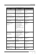
Document History Document History Topic Description Version/Date Issued FIPS 197 Optional support (under SW Version 4.0, Sections: 4.2.5.6.3, 4.2.6.7 license) of FIPS 197 July 2006 compliant encryption 4.9 GHz B&B models AU/SU with 25dBi antennas SW Version 4.0, Section: 1.4, 1.7.1, for point-to-point links in the July 2006 1.7.5.1.1, 1.7.5.4.1 4.9 GHz band AUS functionality change AUS can support up to 8 SW Version 4.0, Section: 1.2, 4.2.6.2.
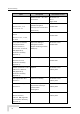
Document History Topic Lost Beacons Transmission Description New feature Watchdog Threshold Version/Date Issued SW Version 4.0, July 2006 Section 4.2.6.2.16 Service Provider Link New feature SW Version 4.0, (VLAN QinQ) Service Provider Link option July 2006 Section 4.2.6.4.1 added to VLAN Link Type. New parameters: Service Provider VLAN ID, VLAN QinQ Protocol Ethertpe. MAC Address List Improved functionality. SW Version 4.0, Section 4.2.6.4.
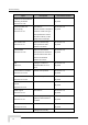
Document History Topic Sections 4.2.3.6, 4.2.3.7 Description (read only, set to unit’s IP Version/Date Issued July 2006 Address) FTP Server IP Address Changed default to SW Version 4.0, Sections 4.2.3.6, 4.2.3.7, 10.0.0.253 July 2006 Number of HW Retries Maximum value was SW Version 4.0, Section 4.2.6.5.7 changed from 15 to 14 July 2006 Ethernet packet length Updated maximum length SW Version 4.0, 4.2.3.11.4 Section 4.2.5.1.
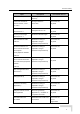
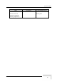
Document History Topic New Subscriber Unit: SU-I Description Version/Date Issued Added new unit – SU-I, and SW Version 4.0 accessories Rev. C August 2006 SU-A-H removed SU-A-H (SU with horizonally SW Version 4.0.27 Sections 1.3.1, 1.7.1, polarized integrated October 2006 1.7.5.1.1, 2.1.1.1 antenna) was removed from products list) IDU PS1036 removed from Replaced by PS1073 Manual. SW Version 4.0.27 October 2006 Sections 1.7.5.1, 1.7.5.4, 2.4, 3.5.
Document History Topic Noise Immunity Control Sections 4.2.6.2.18, Description New feature Version/Date Issued SW Version 4.0.
Legal Rights Legal Rights © Copyright 2007 Alvarion Ltd. All rights reserved. The material contained herein is proprietary, privileged, and confidential and owned by Alvarion or its third party licensors. No disclosure thereof shall be made to third parties without the express written permission of Alvarion Ltd. Alvarion Ltd. reserves the right to alter the equipment specifications and descriptions in this publication without prior notice.
Legal Rights Bug fixes, temporary patches and/or workarounds may be supplied as Firmware updates. Additional hardware, if required, to install or use Firmware updates must be purchased by the Customer. Alvarion will be obligated to support solely the two (2) most recent Software major releases.
Legal Rights GENERATED. ALL OF WHICH ARE EXPRESSLY DISCLAIMED. ALVARION’ WARRANTIES HEREIN RUN ONLY TO PURCHASER, AND ARE NOT EXTENDED TO ANY THIRD PARTIES. ALVARION NEITHER ASSUMES NOR AUTHORIZES ANY OTHER PERSON TO ASSUME FOR IT ANY OTHER LIABILITY IN CONNECTION WITH THE SALE, INSTALLATION, MAINTENANCE OR USE OF ITS PRODUCTS.
Legal Rights and industrial environments. This equipment generates, uses, and can radiate radio frequency energy and, if not installed and used in accordance with the instruction manual, may cause harmful interference to radio communications. Operation of this equipment in a residential area is likely to cause harmful interference in which case the user will be required to correct the interference at the user’s own expense.
Legal Rights possible physiological effects of Radio Frequency Electromagnetic fields have not been yet fully investigated. ANTENNA LIST Including maximum allowed power levels for U-NII/LELAN products operating in the unlicensed 5 GHz bands. FCC ID: LKT-VL-54 (U-NII) Antenna EBW gain MHz IC: 2514A-VL54 (LELAN) calculate Power 7dBm dBi 20 10 20 20 FCC: 21-(20-6) IC: 20.2-(20-6) FCC: 24-(20-6) IC: 23.2-(20-6) FCC ID: LKT-VL-53C (U-NII) Antenna EBW gain MHz FCC: 7 IC: 6.2 FCC: 10 IC: 9.
Legal Rights Outdoor Unit and Antenna Installation and Grounding Ensure that outdoor units, antennas and supporting structures are properly installed to eliminate any physical hazard to either people or property. Make sure that the installation of the outdoor unit, antenna and cables is performed in accordance with all relevant national and local building and safety codes.
Important Notice Important Notice This user manual is delivered subject to the following conditions and restrictions: This manual contains proprietary information belonging to Alvarion Ltd. Such information is supplied solely for the purpose of assisting properly authorized users of the respective Alvarion products.
About This Manual This manual describes the BreezeACCESS VL Broadband Wireless Access System Release 4.0.27 and how to install, operate and manage the system components. This manual is intended for technicians responsible for installing, setting up and operating the BreezeACCESS VL system, and for system administrators responsible for managing the system. This manual contains the following chapters and appendices: Chapter 1 – System description: Describes the BreezeAccess VL system and its components.
About This Manual BreezeACCESS VL devices. In addition, a description of all traps relevant to the BreezeACCESS VL devices is provided. Appendix F – Parameters Summary: Provides an at a glance summary of the configuration parameters, value ranges and default values. Appendix G – Troubleshooting.
Contents Chapter 1 - System Description ..............................................................1 1.1 Introducing BreezeACCESS VL ................................................................................. 2 1.2 Base Station Equipment ............................................................................................. 4 1.2.1 Modular Base Station Equipment ....................................................................... 4 1.2.2 Standalone “Micro-cell” Access Unit ...............
Contents Chapter 2 - Installation ......................................................................... 29 2.1 Installation Requirements.........................................................................................30 2.1.1 Packing List ......................................................................................................30 2.1.2 Indoor-to-Outdoor Cables .................................................................................33 2.2 Equipment Positioning Guidelines ...
Contents 3.2 Using the Optional Y-cable (New SU-A-ODU).......................................................... 69 3.3 Aligning the Subscriber Unit Antenna ..................................................................... 70 3.4 Configuring the Subscriber Unit’s Maximum Modulation Level ............................ 72 3.5 Operation Verification............................................................................................... 74 3.5.1 Outdoor Unit Verification .............................
Contents Appendix E - BreezeACCES VL MIB .................................................... 209 E.1 System Object Identifiers........................................................................................210 E.2 breezeAccessVLMib................................................................................................212 E.2.1 System Information Parameters .....................................................................212 E.2.2 Unit Control Parameters ................................
Contents F.1.8 Security Parameters....................................................................................... 271 Appendix G - Troubleshooting.............................................................273 G.1 Ethernet Port Connection Problems...................................................................... 274 G.2 SU Association Problems....................................................................................... 275 G.3 Low Throughput Problems.................................
Figures Figure 2-1: Threaded Holes/Grooves...............................................................................................................37 Figure 2-2: 3" Pole Installation Using Special Clamps....................................................................................37 Figure 2-3: Back View of the new SU-A-ODU .................................................................................................
Figures Figure 4-1: Main Menu (Administrator Level) .................................................................................................. 83 Figure 4-2: Ethernet Connector Pin Assignments.........................................................................................
Tables Table 1-1: Frequency Bands .............................................................................................................................. 3 Table 1-2: AU Detached Antennas..................................................................................................................... 5 Table 1-3: Subscriber Unit ODU Types ............................................................................................................. 7 Table 1-4: SU-A/E Subscriber Unit Types .....
Tables Table 2-2: Approved Category 5E Ethernet Cables ....................................................................................... 33 Table 2-3: SU-I Panel Components ................................................................................................................. 49 Table 2-4: BS-PS LED Functionality ................................................................................................................ 60 Table 3-1: Basic Parameters ................................
1 Chapter 1 - System Description In This Chapter: Introducing BreezeACCESS VLBWA-VL, page 2 Base Station Equipment, page 4 Subscriber Unit, page 7 BreezeACCESS BWA-VL B&B (4.
Chapter 1 - System Description 1.1 Introducing BreezeACCESS VL BreezeACCESS VL is a high capacity, IP services oriented Broadband Wireless Access system. The system employs wireless packet switched data technology to support high-speed IP services including fast Internet and Virtual Private Networks. BreezeACCESS VL users are provided with a network connection that is always on, supporting immediate access to the Internet and other IP services at high data rates.
Introducing BreezeACCESS VL Table 1-1: Frequency Bands Band Frequencies (GHz) 4.9 4.900 – 5.100 5.2 5.150 – 5.350 5.3 5.250 – 5.350 5.4 5.470 – 5.725 5.8 5.725 – 5.850 The available frequencies, as well as other parameters, depend on applicable local regulations. The actual operating frequencies used by the system can be configured according to applicable radio regulations and specific deployment considerations.
Chapter 1 - System Description 1.2 Base Station Equipment The Access Units, installed at the Base Station site, provide all the functionality necessary to communicate with the Subscriber Units and to connect to the backbone of the Service Provider. There are 2 lines of Access Units with different architectures: Modular Base Station Equipment Standalone “Micro-Cell” Access Unit 1.2.
Base Station Equipment The AU-BS Access Unit can serve up to 512 Subscriber Units (124 when Data Encryption is used). The AUS-BS Access Unit can serve up to 8 SU-3 and/or SU-6 and/or SU-I Subscriber Units. NOTE For convenience, all references to AU-BS are applicable also for AUS-BS, unless explicitly stated otherwise. The AU-D/E-BS-ODU outdoor unit contains the processing and radio modules and connects to an external antenna using a short RF cable. E model units are supplied without an antenna.
Chapter 1 - System Description 1.2.2 Standalone “Micro-cell” Access Unit The standalone AU-D/E-SA Access Unit is very similar to the AU-D/E-BS unit. The AU-D/E-SA-ODU outdoor unit is very similar to the AU-D/E-BS-ODU outdoor unit (identical functionality, but the units are not interchangeable). The available antennas for D model units are the same as those of the AU-D-BS Access Unit.
Subscriber Unit 1.3 Subscriber Unit The Subscriber Unit (SU) installed at the customer premises enables the customer data connection to the Access Unit. The Subscriber Unit provides an efficient platform for high speed Internet and Intranet services. The use of packet switching technology provides the user with a connection to the network that is always on, enabling immediate access to services.
Chapter 1 - System Description New SU-A-ODU SU-A-ODU and IDU For each ODU type, several models are available to support various end-users needs and applications, as detailed in Table 1-4: Table 1-4: SU-A/E Subscriber Unit Types SU Type Description SU-54-BD A high-rate CPE that supports a full LAN SU-6-1D A medium rate CPE that supports a single Ethernet device (one MAC address) SU-6-BD A medium rate CPE that supports a full LAN SU-3-1D An entry level CPE that supports a single Ethernet device (
Subscriber Unit Table 1-5: SU-I Subscriber Units SU-I Configuration SU-I-D Description All-indoor medium rate CPE supporting a full LAN, and a wall/window antenna kit SU-I-E All-indoor medium rate CPE supporting a full LAN (antenna not included) The SU-I is currently available in the 5.4 GHz and 5.8 GHz bands. NOTE It is recommended to pre-configure the units prior to shipment to end-users. 1.3.
Chapter 1 - System Description 1.4 BreezeACCESS VL B&B (4.9 GHz only) BreezeACCESS VL B&B is available in the 4.9 GHz band to support point-topoint applications. A B&B point-to-point link includes: AU-D-SA-4.9-6-VL: A standalone AU with a 25 dBi, 6° high gain directional antenna. SU-D-4.9-54-BD-VL: SU-54-BD with a 25 dBi, 6° high gain directional antenna.
Networking Equipment 1.5 Networking Equipment The Base Station equipment is connected to the backbone through standard data communication and telecommunication equipment. The 10/100BaseT ports of the AU modules can be connected directly to a multi-port router or to an Ethernet switch connected to a router. The point-to-point link from the Base Station to the backbone can be either wired or wireless. Data to the Internet is routed to the backbone through standard routers.
Chapter 1 - System Description 1.6 Management Systems The end-to-end IP-based architecture of the system enables full management of all components, from any point in the system. BreezeACCESS VL components can be managed using standard management tools through SNMP agents that implement standard and proprietary MIBs for remote setting of operational modes and parameters. The same SNMP management tools can also be used to manage other system components including switches, routers and transmission equipment.
Management Systems AlvariSTAR provides the following BWA network management functionality: Device Discovery Device Inventory Topology Fault Management Configuration Management Performance Monitoring Device embedded software upgrade Security Management Northbound interface to other Network Management Systems or OSS.
Chapter 1 - System Description 1.7 Specifications 1.7.1 Radio Table 1-6: Radio Specifications Item Frequency Description 1 4.9 GHz Family: 4.900 – 5.100 GHz 5.2 GHz Family: 5.150 – 5.350 GHz 5.3 GHz Family: 5.250 – 5.350 GHz 5.4 GHz Family: 5.470 – 5.725 GHz 5.8 GHz Family: 5.725 – 5.
Specifications Table 1-6: Radio Specifications Item Description AU-Ant-5G-17-90: 17 dBi typical, 5.150-5.875 GHz, o o 90 horizontal x 6 vertical sector antenna, vertical polarization, compliant with EN 302 085 V1.1.2 CS3 AU-Ant-5G-15-120: 15 dBi typical, 5.150-5.875 GHz, o o 120 horizontal x 6 vertical sector antenna, vertical polarization, compliant with EN 302 085 V1.1.2 CS3. AU-Ant-4.9G-15-120: 15 dBi typical, 4.900-5.100 GHz, o o 124 horizontal x 6.
Chapter 1 - System Description 4 Modulation Level indicates the radio transmission rate and the modulation scheme. Modulation Level 1 is for the lowest radio rate and modulation scheme. 5 Modulation Level 8 is supported only in units with HW Revision B and above.
Specifications 1.7.2 Data Communication Table 1-7: Data Communication Item Description Standard compliance IEEE 802.3 CSMA/CD VLAN Support Based on IEEE 802.1Q Layer-2 Traffic Prioritization Based on IEEE 802.
Chapter 1 - System Description 1.7.
Specifications 1.7.4 Standards Compliance, General Table 1-9: Standards Compliance, General Type EMC Standard FCC Part 15 class B ETSI EN 300 489-1 Safety UL 1950 EN 60950 Environmental Operation ETS 300 019 part 2-3 class 3.2E for indoor ETS 300 019 part 2-4 class 4.1E for outdoor Lightning protection Storage ETS 300 019-2-1 class 1.2E Transportation ETS 300 019-2-2 class 2.3 EN 61000-4-5, Class 3 (2kV) (AU-ODU Antenna connection) Radio FCC Part 15.
Chapter 1 - System Description 1.7.5 Physical and Electrical 1.7.5.1 SU-A/E Subscriber Unit NOTE In the 5.4 and 5.8 GHz band, the equipment may be shipped with a new, smaller size SU-A-ODU that supports both horizontal and vertical polarization. 1.7.5.1.1 Mechanical Table 1-10: Mechanical Specifications, SU-A/E Subscriber Unit Unit General Structure Dimensions (cm) Weight (kg) 14 x 6.6 x 3.5 0.3 41.5 x 36.9 x 6.3 2.3 22 x 22 x 7 1.3 30.5 x 11.7 x 5.7 1.
Specifications 1.7.5.1.
Chapter 1 - System Description 1.7.5.2 SU-I Subscriber Unit 1.7.5.2.1 Mechanical and Electrical Table 1-13: Mechanical and Electrical Specifications, SU-I Subscriber Unit Item Details Dimensions (cm) 11.8 (H) x 20 (L) x 3.1 (W) Weight (g) 600 Power Consumption 15W maximum DC Power Input (from Power Supply) 48 VDC Mains Power Input (to Power Supply) 90-265 VAC, 47-63 Hz 1.7.5.2.
Specifications 1.7.5.3 Modular Base Station Equipment 1.7.5.3.1 Mechanical Table 1-15: Mechanical Specifications, Modular Base Station Equipment Unit Structure Dimensions (cm) Weight (kg) BS-SH 19" rack (3U) or desktop 13 x 48.2 x 25.6 4.76 BS-PS-DC DC power supply module 12.9 x 7.0 x 25.3 1.2 BS-PS-AC AC power supply module 12.9 x 7.0 x 25.3 1.2 BS-AU Indoor module of the 12.9 x 3.5 x 25.5 0.15 AU-D-BS access unit AU-D-BS-ODU pole or wall mountable 30.5 x 11.7 x 5.7 1.
Chapter 1 - System Description 1.7.5.3.2 Connectors Table 1-16: Connectors, Modular Base Station Equipment Unit Connector BS-AU 10/100 BaseT Description 10/100BaseT Ethernet (RJ-45) with 2 embedded LEDs.
Specifications Table 1-18: Mechanical Specifications, Stand Alone Access Unit Unit Structure General Dimensions (cm) Weight (kg) An IDU indoor unit and an AU-D-BS-ODU outdoor unit connected to a detached antenna IDU PS1073 Plastic box (black), desktop or wall 14 x 6.6 x 3.5 0.3 mountable AU-D-SA-ODU Poll or wall mountable 30.5 x 11.7 x 5.7 1.8 AU-Ant-5G-16-60 2"-3.5" pole mountable 43.6 x 25 x 1.0 2.2 AU-Ant-5G-17-90 2"-3.5" pole mountable 55 x 25 x 1.1 1.5 AU-Ant-5G-15-120 2"-3.
Chapter 1 - System Description 1.7.5.4.3 Electrical Table 1-20: Electrical Specifications, Stand Alone Access Unit Unit Details General Power consumption: 25W IDU AC power input: 85-265 VAC, 50-60 Hz AU-D-SA-ODU 54 VDC from the IDU over the indoor-outdoor Ethernet cable 1.7.5.5 25dBi Antenna (for B&B point-to-point link) Table 1-21: 25dBi Antenna Specifications Item Description Regulatory Compliance ETSI EN 302 085 V1.1.2 (2001-02) Range1 Frequency Range 4.900-5.100 GHz Gain 25dBi min.
Specifications 1.7.5.6 SU-I-D Wall/Window Detached Antenna Table 1-22: SU-I-D Wall/Window Detached Antenna Specifications Item Description Frequency Range 5.150-5.875 GHz Gain 15dBi net (excluding cable loss). Azimuth Beamwidth 45 ~55° Elevation Beamwidth 10°~12° Polarization Linear (Vertical) Dimensions (cm) 33 x 9.3 x 2.1 Weight (g) 190 Connector SMA jack Cable 2 meter, 2 x SMA plug, 3.6 dB max insertion loss 1.7.
2 Chapter 2 - Install ation In This Chapter: Installation Requirements, page 30 Equipment Positioning Guidelines, page 34 Installing the Outdoor Unit, page 36 Installing the Universal IDU Indoor Unit, page 46 Installing the SU-I, page 48
Chapter 2 - Installation 2.1 Installation Requirements This section describes all the supplies required to install the BreezeACCESS VL system components and the items included in each installation package. NOTE Installation requirements for SU-I are provided in section 2.5 on page 48. 2.1.1 Packing List 2.1.1.
Installation Requirements An IDU to ODU cable kit, including 20m Category 5E Ethernet cable with a shielded RJ-45 connector crimped on one end, a waterproof sealing assembly and two shielded RJ-45 connectors (not applicable for the new SU-A-ODU). 2.1.1.2 Modular Base Station Equipment This section describes the items included in the installation packages for each Modular Base Station system component. 2.1.1.2.
Chapter 2 - Installation DC power cable 2.1.1.3 AU-D/E-SA Standalone Access Unit The AU-D/E-SA installation kit includes the following components: IDU indoor unit with a wall mounting kit Mains power cord AU-D/E-SA-ODU outdoor unit Pole mounting kit for the AU-D/E-SA-ODU In AU-D-SA kits: Antenna, including pole mounting hardware RF cable 2.1.1.
Installation Requirements Portable PC with Ethernet card and Telnet software or BreezeCONFIG for BreezeACCESS VL* application and a crossed Ethernet cable Installation tools and materials, including appropriate means (e.g. a pole) for installing the outdoor unit. 2.1.2 Indoor-to-Outdoor Cables NOTE The length of the indoor-to-outdoor Ethernet cable should not exceed 90 meters.
Chapter 2 - Installation 2.2 Equipment Positioning Guidelines This section provides key guidelines for selecting the optimal installation locations for the various BreezeACCESS VL system components. CAUTION ONLY experienced installation professionals who are familiar with local building and safety codes and, wherever applicable, are licensed by the appropriate government regulatory authorities should install outdoor units and antennas.
Equipment Positioning Guidelines The indoor equipment should be installed as close as possible to the location where the indoor-to-outdoor cable enters the building. The location of the indoor equipment should take into account its connection to a power outlet and the customer’s equipment.
Chapter 2 - Installation 2.3 Installing the Outdoor Unit The following sections describe how to install the outdoor units, including pole mounting the ODU, and connecting the indoor-to-outdoor, grounding and RF cables. NOTE Ensure that outdoor units, antennas and supporting structures are properly installed to eliminate any physical hazard to either people or property.
Installing the Outdoor Unit Figure 2-1: Threaded Holes/Grooves Figure 2-2 illustrates the method of mounting an outdoor unit on a pole, using the clamps and threaded rods. Figure 2-2: 3" Pole Installation Using Special Clamps NOTE There is a groove on one end of the threaded rod. Be sure to insert the threaded rods with the grooves pointing outward, as these grooves enable you to use a screwdriver to fasten the rods to the unit.
Chapter 2 - Installation 2.3.2 Pole Mounting the New SU-A-ODU The new SU-A-ODU can be mounted on a 1" to 4" pole using one of the following options: A pole mounting kit is supplied with each unit. The kit includes a special clamp and a pair of threaded rods, flat washers, spring washers and nuts. There are two pairs of threaded holes on the back of the unit, enabling to use the mounting kit for installing the unit using either vertical or horizontal polarization.
Installing the Outdoor Unit For horizontal polarization install the unit with the Polarization Arrow pointing sideward and the connectors facing downward. 2.3.2.2 Pole Mounting the ODU Using the Clamp Figure 2-4 and Figure 2-5 illustrate how to mount an ODU on a pole, using the clamp and threaded rods. NOTE There is a groove on one end of the threaded rod. Be sure to insert the threaded rods with the grooves pointing outward, and fasten them to the unit using a screwdriver.
Chapter 2 - Installation Figure 2-5: New SU-A-ODU Pole Installation Using the Special Clamp, Horizontal Polarization 40 BreezeACCESS VL System Manual
Installing the Outdoor Unit 2.3.2.3 Pole Mounting the ODU with the Tilt Accessory Figure 2-6: New SU-A-ODU Pole Installation Using the Tilt Accessory, Vertical Polarization To mount the ODU on a pole using the Tilt accessory: 1 Attach the Tilt accessory to the ODU using the two pairs of flat washers, spring washers and nuts supplied in the Tilt kit. 2 Mount the Tilt accessory on a 1" to 4" pole using two 9/16" metal bands.
Chapter 2 - Installation 2.3.3 Connecting the Grounding and Antenna Cables The Grounding screw (marked ) is located on the bottom panel of the outdoor unit (in the new SU-A-ODU it is located on the backside of the unit). The Antenna RF connector (marked ) is located on the top panel of the AU-ODU/SU-E-ODU. To connect the grounding cable: 1 Connect one end of a grounding cable to the grounding terminal and tighten the grounding screw firmly.
Installing the Outdoor Unit Figure 2-8: Bottom Panel of the New SU-A-ODU (without IDU COM Sealing Cap) NOTE The MAC Address of the unit is marked on both the ODU and the indoor unit (on the print side of the BS-AU module or on the bottom side of the Universal IDU). If for any reason the ODU is not used with the IDU with which it was shipped, the MAC Address of the system is in accordance with the marking on the ODU. 2.3.4 Connecting the Indoor-to-Outdoor Cable 2.3.4.
Chapter 2 - Installation 3 Route a straight Category 5E Ethernet cable (8-wire, 24 AWG) through both the top nut and the waterproof seal. NOTE Use only Category 5E 4x2x24# FTP outdoor cables from an approved manufacturer. See list of approved cables and length limitations in section 2.1.2. 4 Insert and crimp the RJ-45 connector. Refer to Appendix D for instructions on preparing the cable. 5 Connect the Ethernet cable to the outdoor unit RJ-45 connector.
Installing the Outdoor Unit Figure 2-10: Inserting the IDU COM Cable into the Sealing Cap 2 Connect the Ethernet cable to the IDU COM RJ-45 connector. 3 Put the sealing cap back in its place. Make sure that the small protrusion on the side of the cap fits inside the hole on the connector's protective body. Figure 2-11: Connecting the IDU COM connector and inserting the Sealing Cap 4 Use appropriate sealing material to protect the connection against moisture and humidity.
Chapter 2 - Installation 2.4 Installing the Universal IDU Indoor Unit The unit can be placed on a desktop or a shelf. Alternatively, it may be wall-mounted using the kit supplied with the unit. Figure 2-12: IDU PS 1073 Front Panel The RADIO connector and RESET button are located on the front panel, the ETHERNET connector is located on the side panel and LEDs are located on the top panel. CAUTION Do not connect the data equipment to the RADIO port.
Installing the Universal IDU Indoor Unit NOTE The length of the Ethernet cable connecting the indoor unit to the user's equipment, together with the length of the Indoor-to-Outdoor cable, should not exceed 100 meters. 2.4.1 RESET Button Functionality Using a sharp object, press the recessed RESET button for a short time to reset the unit and reboot from the Main version. In units with ODU HW revision C and an IDU PS 1073, the RESET button can be used for setting the unit to its factory defaults.
Chapter 2 - Installation 2.5 Installing the SU-I The following sections describe how to install the SU-I CPE. 2.5.1 Installation Requirements 2.5.1.1 Packing List SU-I CPE Power Adapter 3 meters Ethernet Cable Wall/window mountable detached antenna kit, including wall/window mounting accessories and a 2 meters SMA-SMA (M/M) RF cable (only with SU-I-D). 2.5.1.2 Additional/Optional Items Wall Mounting Bracket kit for the SU-I CPE*.
Installing the SU-I 2.5.2 SU-I Connectors and LEDs Figure 2-13: SU-I Panel Table 2-3: SU-I Panel Components Name Status Description Functionality Self-test and power Green: Power is available and self-test passed. indication Blinking Amber: Testing (not ready for operation) Red: Self-test failed.
Chapter 2 - Installation Name Description SNR bar Functionality Received signal Red LED: Signal is too low (SNR < 4dB). strength Indication 8 green LEDs: Quality of the received signal. Orange LED: Signal is too high (SNR > 50dB).
Installing the SU-I 2 Verify that the green Status LED located on the unit's front panel illuminates, indicating that the power supply to the unit is OK and self test passed successfully. 3 Connect the RF cable supplied with the antenna to the SMA jack located on the unit’s front panel. Install the antenna using the instructions provided in Section 2.5.5 on page 52, and connect to it the other end of the RF cable. Do not over-tighten the SMA connectors.
Chapter 2 - Installation Figure 2-14: SU-I Wall Mount 2.5.5 Installing the Detached Antenna The detached antenna kit includes the following components: ALA04-200160 panel antenna 2 meter SMA-SMA (M/M) RF cable Simple wall mounting kit, enabling installation on a wall (without any capability for adjusting the direction). For installation instructions see Section 2.5.5.1. Wall mounting kit with rotation capability, enabling installation on a wall with capability for adjusting the direction.
Installing the SU-I Simple window mounting accessories, enabling installation on a glass window (without any capability for adjusting the direction). For installation instructions see Section 2.5.5.3. Window mounting kit with rotation capability, enabling installation on a glass window (with rotation capability for adjusting the direction). For installation instructions see Section 2.5.5.4.
Chapter 2 - Installation Figure 2-15: Wall Mounting the Antenna 2.5.5.2 Wall Mount with Rotation Capability The installation kit includes 4 L-type mounting plates (one top, one bottom, one Wall-V and one Wall-H), 6 M5 screws (with washers and spring washers), 2 plastic anchors and 2 #8 screws. 1 If anchors are needed (wall-board, plaster board, etc.), drill two holes (361 mm apart) for the anchors using a 5 mm drill bit and insert anchors.
Installing the SU-I 4 Attach the assembled plates to the flat rear-side of the antenna. Use the two remaining M5 screws to fasten them. 5 Fasten the antenna to the wall. Use the two #8 screws provided with the kit. Do not over tighten. 6 Connect the antenna cable to the connector located on the bottom side of the antenna. Use only the torque key supplied with the antenna. Do not over tighten. Do not use a wrench or a similar tightening tool.
Chapter 2 - Installation 2.5.5.3 Window Mount The installation kit includes 2 suction cups. 1 2 Attach the suction cups to the antenna. Refer to Figure 2-17 for directions. Determine the location of the antenna on the glass. Attach it to the window by pressing the suction cups onto the glass. 3 Connect the antenna cable to the connector located on the bottom side of the antenna. Use only the torque key supplied with the antenna. Do not over tighten. Do not use a wrench or a similar tightening tool.
Installing the SU-I 2.5.5.4 Window Mount with Rotation Capability The installation kit includes the following: 4 PHK40*16PT screws (1), 2 M4 washers (2), 2 rotation bars (3) and 2 suction cups (4). 1 Attach the rotation bars to the antenna and the suction cups to the rotation bars. Refer to Figure 2-18 for directions. 2 Determine the location of the antenna on the glass. Attach it to the window by pressing the suction cups onto the glass.
Chapter 2 - Installation Figure 2-18: Window Mounting with Rotation Capability 58 BreezeACCESS VL System Manual
Installing the Modular Base Station Equipment 2.6 Installing the Modular Base Station Equipment The following sections describe the slot assignment for the Base Station chassis, provide illustrated descriptions of the power supply modules and Access Unit network interface modules, and describe how to install the Base Station equipment. 2.6.1 BS-SH Slot Assignment The Base Station chassis comprises ten slots, as shown in Figure 2-19.
Chapter 2 - Installation 2.6.2 BS-PS-AC Power Supply Module The BS-PS-AC is an AC to DC converter that provides power to all the BS-AU modules installed in the BS-SH chassis. Figure 2-20 shows the BS-PS-AC front panel. Figure 2-20: BS-PS-AC Front Panel The BS-PS-AC includes a power input connector, marked AC IN, for connecting the AC power cord to the mains. The ON/OFF Power Switch controls the flow of mains power to the power supply module.
Installing the Modular Base Station Equipment 2.6.3 BS-PS-DC Power Supply Module The BS-PS-DC is a DC-to-DC converter that provides power to all the BS-AU modules installed in the BS-SH chassis. Figure 2-21 shows the BS-PS-DC front panel. Figure 2-21: BS-PS-DC Front Panel The BS-PS-DC provides a power input connector, marked -48VDC, for connecting the -48 VDC power source to the module.
Chapter 2 - Installation 2.6.4 BS-AU Network Interface Module Figure 2-22 shows the front panel of the BS-AU Access Unit Network Interface module. Figure 2-22: BS-AU Front Panel The BS-AU provides the following interfaces: 10/100 BaseT: A 10/100BaseT Ethernet connector for connecting the BS-AU to the network. A straight Ethernet cable should be used to connect the module to a hub, router or switch. RADIO: A 10/100BaseT Ethernet connector for connecting the BS-AU to an AU-ODU outdoor unit.
Installing the Modular Base Station Equipment 2.6.5 Installing the BS-SH Chassis and Modules This section describes how to install the power supply and Access Unit network interface modules in the Base Station chassis. To install the BS SH chassis and modules: 1 Install the BS-SH chassis in a 19” cabinet. To prevent over-heating, leave a free space of at least 1U between the upper/lower covers of the BS-SH chassis and other units in the cabinet.
Chapter 2 - Installation OVERTEMP alarm indicator is off. Refer to Table 2-4 for a description of these LEDs. 11 Configure the basic parameters in all BS-AU modules as described in section 3.1. 12 Connect the 10/100 BaseT LAN connector(s) to the network. The cable connection should be straight Ethernet if connecting the indoor unit to a hub/switch and a crossed cable if connecting it directly to a PC Network Interface Card (NIC).
3 Chapter 3 - Commissioning About This Chapter: Configuring Basic Parameters, page 66 Using the Optional Y-cable (New SU-A-ODU), page 69 Aligning the Subscriber Unit Antenna, page 70 Configuring the Subscriber Unit’s Maximum Modulation Level, page 72 Operation Verification, page 74
Chapter 3 - Commissioning 3.1 Configuring Basic Parameters After completing the installation process, as described in the preceding chapter, the basic parameters must be configured to ensure that the unit operates correctly. After the basic parameters have been configured, additional parameters can be remotely configured via the Ethernet port or the wireless link using Telnet or SNMP management, or by loading a configuration file. Refer to section 4.
Configuring Basic Parameters Table 3-1: Basic Parameters Parameter Default Value Sub-Band Comment Maximum Tx Power parameter. Maximum Tx Power (SU) Dependent on HW Maximum Tx Power revision and Sub-Band cannot be higher than the upper limit according to the Sub-Band in use. Tx Power (AU) On Antenna Gain (units with external According to the antenna If set to “Not Set Yet”, antenna) supplied with the unit and must be configured the Sub-Band.
Chapter 3 - Commissioning Table 3-1: Basic Parameters Parameter Default Value Authentication Algorithm Open System Data Encryption Option Disable Security Mode WEP Default Multicast Key (AU) Key 1 Promiscuous Authentication (AU) Disable Default Key (SU) Key 1 Key 1 to Key 4 00……0 (32 zeros, Comment Availability of security parameters depends on support according to the country code.
Using the Optional Y-cable (New SU-A-ODU) 3.2 Using the Optional Y-cable (New SU-A-ODU) A special Y-cable, available from Alvarion, enables to connect a a portable PC directly to the IDU COM port of the SU-A-ODU. This enables the installer to perform the entire process of configuring basic parameters, aligning the antenna and verifying proper operation of the unit right after completing the installation, minimizing the number of times the installer must climb to the roof.
Chapter 3 - Commissioning 3.3 Aligning the Subscriber Unit Antenna NOTE This antenna alignment process described in this section is applicable to both the SU-A-ODU and the SU-I antenna, unless stated otherwise. The SNR bar display is located on the bottom panel of the SU-A-ODU/front panel of the SU-I indoor unit. The ten LEDs indicate the quality of the received signal. The higher the number of green LEDs indicating On, the higher the quality of the received signal.
Aligning the Subscriber Unit Antenna NOTE In some cases, the antenna may need to be tilted to ensure that the level at which the SU receives transmissions from the AU (and vice versa) is not too high. As a rule of thumb, if the SU is located at a distance of less than 300 meters from the AU, it is recommended to up-tilt the antenna by approximately 10° to 15°. To guarantee a safety margin from the saturation level (received signal of –40 dBm at the antenna port), the SNR should not be higher than 50 dB.
Chapter 3 - Commissioning 3.4 Configuring the Subscriber Unit’s Maximum Modulation Level This section describes how to configure the maximum modulation level for Subscriber Units. NOTE If the unit is associated with the AU, then the final configuration of the Maximum Modulation Level parameter may be performed remotely, for example, from the site of the AU or from another site.
Configuring the Subscriber Unit’s Maximum Modulation Level Table 3-2: Recommended Maximum Modulation Level* SNR Maximum Modulation Level SNR > 23 dB 8 21 dB < SNR < 23 dB 7 16 dB < SNR < 21 dB 6 13 dB < SNR < 16 dB 5 10 dB < SNR < 13 dB 4 8 dB < SNR < 10 dB 3 7 dB < SNR < 8 dB 2 6 dB < SNR < 7 dB 1 * The maximum supported value depends on the unit’s HW revision and on the Max Modulation Level according to the Sub-Band.
Chapter 3 - Commissioning 3.5 Operation Verification The following sections describe how to verify the correct functioning of the Outdoor Unit, Indoor Unit, Ethernet connection and data connectivity. 3.5.1 Outdoor Unit Verification To verify the correct operation of the Outdoor Unit, examine the LED indicators located on the bottom panel of the outdoor unit. The following tables list the provided LEDs and their associated indications.