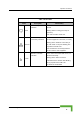
Operation Verification Table 3-4: SU-ODU LEDs Name W-LINK Description Wireless Link Indictor Functionality Green – Unit is associated with an AU, no wireless link activity Blinking Green – Data received or transmitted on the wireless link. Blinking rate is proportional to wireless traffic rate Off – Wireless link is disabled Status Self-test and power indication Green – Power is available and self-test passed.
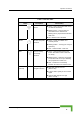
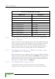
Chapter 3 - Commissioning Table 3-5: SU-ODU SNR Bar LED Functionality SNR Bar LEDs 76 SNR (typical) LED 1 (red) is On Signal is too low (SNR < 4 dB) LED 2 (green) is On SNR > 4 dB LEDs 2 to 3 (green) are On SNR > 8 dB LEDs 2 to 4 (green) are On SNR > 13 dB LEDs 2 to 5 (green) are On SNR > 19 dB LEDs 2 to 6 (green) are On SNR > 26 dB LEDs 2 to 7 (green) are On SNR > 31 dB LEDs 2 to 8 (green) are On SNR > 38 dB LEDs 2 to 9 (green) are On SNR > 44 dB LEDs 2 to 9 (green) and 10 (orange) ar
Operation Verification 3.5.2 Indoor Unit Verification To verify the correct operation of the indoor equipment, examine the LED indicators located on the top panel of the SU IDU and AU IDU units, or on the front panel of the BS-AU module. Table 3-6 provides information for the BS-AU IDU LEDs. Table 3-7 lists the LEDs of the PS1073 IDU. Table 3-6: BS-AU LEDs Name W-LINK Description Wireless link activity Functionality Green - At least one SU is associated. Blinking Red - No SU is associated.
Chapter 3 - Commissioning Table 3-7: PS1073 SU IDU / AU-SA IDU LEDs Name Description Functionality Green – Self-test passed and Ethernet connection confirmed by the outdoor unit (Ethernet integrity check passed). 3.5.3 SU-I Unit Verification To verify the correct operation of the SU-I unit, examine the LED indicators located on the front panel of the SU-I unit. The following tables list the provided LEDs and their associated indications.
Operation Verification Table 3-8: SU-I LEDs Name Description Functionality Self-test and power Green: Power is available and self-test indication passed. Status Blinking Amber: Testing (not ready for operation) Red: Self-test failed. Fatal error Ethernet activity/ Green: Ethernet link between the SU-I and connectivity indication the data equipment is detected, no activity Blinking Green: Ethernet connectivity is Ethernet OK, with traffic on the port. Blinking rate proportional to traffic rate.
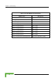
Chapter 3 - Commissioning Table 3-9: SU-I SNR Bar LED Functionality SNR Bar LEDs 3.5.
4 Chapter 4 - Oper ation and Administration In This Chapter: Working with the Monitor Program, page 82 Menus and Parameters, page 85
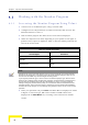
Chapter 4 - Operation and Administration 4.1 Working with the Monitor Program 4.1.1 Accessing the Monitor Program Using Telnet 1 Connect a PC to the Ethernet port, using a crossed cable. 2 Configure the PC's IP parameters to enable connectivity with the unit. The default IP address is 10.0.0.1. 3 Run the Telnet program. The Select Access Level menu is displayed. 4 Select the required access level, depending on your specific access rights. A password entry request is displayed.
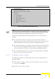
Working with the Monitor Program BreezeACCESS VL/AU Official Release Version – 4.0.27 Release Date: Feb 13 2007, 12:59:23 Main Menu ========== 1 – Info Screens 2 – Unit Control 3 - Basic Configuration 4 – Site Survey 5 - Advanced Configuration x - Exit >>> Figure 4-1: Main Menu (Administrator Level) NOTE If the Telnet session is not terminated properly; for example, if you simply close the window, the monitor program is blocked for several minutes.
Chapter 4 - Operation and Administration NOTE The program is automatically terminated following a determined period of inactivity. The default time out is 5 minutes and is configured with the Log Out Timer parameter. In some cases, to activate any configuration changes, you must reset the unit. Certain settings are automatically activated without having to reset the unit.
Menus and Parameters 4.2 Menus and Parameters The following sections describe the menus and parameters provided by the Monitor program. 4.2.1 Main Menu The Main Menu enables to access the following menus, depending on your access level, as described in section 4.1. Info Screens: Provides a read only display of current parameter values. Available at all access levels.
Chapter 4 - Operation and Administration Show Advanced Configuration Show Country Dependent Parameters Show All Parameters 4.2.2.1 Show Unit Status The Show Unit Status menu is a read only menu that displays the current values of the following parameters: Unit Name: As defined in the Unit Control menu. Unit Type: Identifies the unit's function: AU-BS, AU-SA, AUS-BS, AUS-SA, SU-3-1D, SU-6-1D, SU-6-BD, SU-54-BD, SU-I. Unit MAC Address: The unit's unique IEEE MAC address.
Menus and Parameters AU MAC Address (SU only): The MAC address of the AU with which the unit is currently associated. If the unit is not associated with any AU, the address defaults to the IEEE broadcast address, which is FF-FF-FF-FF-FF-FF. Unit Hardware Version: The version of the outdoor unit hardware. Unit BOOT Version: The version of the BOOT SW. Time Since Last Reset Flash Versions: Running from: Shows whether the unit is running from the Main or from the Shadow Version.
Chapter 4 - Operation and Administration FTP Parameters: General FTP parameters (common to SW Version Download, Configuration File Upload/Download and Event File Upload using FTP): FTP Server IP Address FTP Gateway IP Address FTP User Name FTP Password FTP Software Download Parameters: The parameters for SW download using FTP, as defined in Unit Control menu.
Menus and Parameters 4.2.2.3 Show Advanced Configuration The Show Advanced Configuration menu enables to access the read only sub menus that display the current values of the parameters included in the applicable sub menus of the Advanced Configuration menu. 4.2.2.4 Show Country Dependent Parameters Each country has its radio regulation regarding transmissions in the applicable bands that affect parameters such as available frequencies, bandwidth, transmit power, etc.
Chapter 4 - Operation and Administration Max Modulation Level: The highest allowed modulation level. Burst Mode: Indicates whether Burst Mode operation is allowed. Maximum Burst Duration: If Burst Mode is allowed, this parameter displays the upper limit for the Maximum Burst Duration. DFS Option: Indicates whether the DFS (Dynamic Frequency Selection) mechanism for identification and avoidance of channels with radar activity is supported.
Menus and Parameters Ethernet Port Negotiation Mode Change System Location Event Log Menu Feature Upgrade 4.2.3.1 Reset Unit The Reset Unit option enables resetting the unit. After reset, any modifications made to the system parameters are applied. 4.2.3.2 Default Settings The Set defaults submenu enables resetting the system parameters to a predefined set of defaults or saving the current configuration as the set of Operator Defaults.
Chapter 4 - Operation and Administration Set Partial Factory Defaults Set Complete Operator Defaults Set Partial Operator Defaults Cancel Current Pending Request 4.2.3.2.1.1 Set Complete Factory Defaults Select this option to reset the unit to the standard Factory Defaults configuration, excluding several parameters that are listed in Table 4-2.
Menus and Parameters Table 4-3: Parameters that are not reset after Set Partial Factory/Operator Defaults Parameters Group Unit Control parameters Parameter Passwords Ethernet Port Negotiation Mode FTP Server IP address FTP Gateway IP Address FTP User Name FTP Password IP Parameters IP Address Subnet Mask Default Gateway Address DHCP Option Access to DHCP Security Parameters Authentication Algorithm Default Key (SU) Data Encryption Mode Default Multicast Key (AU) Security Mode Key # 1 to Key # 4 Oper
Chapter 4 - Operation and Administration Table 4-3: Parameters that are not reset after Set Partial Factory/Operator Defaults Parameters Group Air Interface Parameters Parameter ESSID Operator ESSID Option (AU) Operator ESSID (AU) Cell Distance Mode (AU) Maximum Cell Distance (AU) Per SU Distance Learning Option (AU) Selected Sub-Band (AU) Frequency (AU) DFS Option (AU) SU Waiting Option (AU) Channel Reuse Option (AU) Radar Activity Assessment Period (AU) Maximum Number of Detections in Assessment Period
Menus and Parameters Table 4-3: Parameters that are not reset after Set Partial Factory/Operator Defaults Parameters Group Bridge Parameters Parameter VLAN ID – Management Service Provider VLAN ID (SU) VLAN QinQ Protocol Ethertype MAC Address List (AU) MAC Address List Action (AU) Service Parameters DRAP Option (AU) UDP Port (AU) Max Number of Voice Calls (AU) DRAP TTL (AU) Wireless Link Prioritization Option (AU) Low Priority AIFS (AU) Number of HW Retries for High Priority Traffic (AU) Number of HW Re
Chapter 4 - Operation and Administration 4.2.3.2.1.5 Cancel Current Pending Request After selecting one of the Set defaults options, it will be executed after the next reset. This option enables to cancel the pending request before execution (provided the unit has not been reset yet). 4.2.3.2.2 Save Current Configuration As Operator Defaults The Save Current Configuration As Operator Defaults enables defining the current configuration of the unit as the Operator Defaults configuration. 4.2.3.
Menus and Parameters Reset and Boot from Shadow Version: Activates the shadow (backup) software version. The unit is reset automatically. Following the next reset the unit will switch to the main version. Use Running Version After Reset: Defines the current running version as the new main version. This version will also be used following the next reset. 4.2.3.6 SW Version Download The SW Version Download submenu enables the optional downloading of a SW Version file from a remote FTP server.
Chapter 4 - Operation and Administration Valid values: A string of up to 18 printable ASCII characters. The default is: vx FTP Password: The FTP Password option enables defining the password to be used for accessing the FTP server that is hosting the SW Version file. Valid values: A string of up to 18 printable ASCII characters.
Menus and Parameters Valid values: A string of up to 80 printable ASCII characters. To clear the field press "." The default is an empty string. Configuration File FTP File Name: The Configuration File FTP File Name option enables defining the name of the configuration file to be uploaded/downloaded. Valid values: A string of up to 20 printable ASCII characters. An empty string is not allowed. The default is config.cfg.
Chapter 4 - Operation and Administration Show Configuration File Upload/Download Parameters: Displays the current values of the Configuration File Upload/Download parameters. NOTE There is one set of general FTP parameters (FTP Server IP Address, FTP Gateway IP Address, FTP User Name and FTP Password). This set (or relevant parts of the set) serves the SW Download procedure, the Configuration File Upload/Download procedure and the Event Log File Upload procedure.
Menus and Parameters 4.2.3.11 Event Log Menu The Event Log Menu enables controlling the event log feature. The event log is an important debugging tool and a flash memory sector is dedicated for storing it. Events are classified according to their severity level: Message (lowest severity), Warning, Error or Fatal (highest severity). The severity level of events that should be saved in the Event Log is configurable. Events from the configured severity and higher are saved and may be displayed upon request.
Chapter 4 - Operation and Administration 4.2.3.11.4 Event Log Upload The Event Log Upload submenu enables the optional uploading of the event log file to a remote FTP server. The Event Log Upload submenu includes the following options: FTP Event Log Upload Execute: The FTP event Log Upload Execute executes the upload of the Event Log file according to the parameters defined below.
Menus and Parameters Show FTP Event Log File Upload Parameters: Displays the current values of the Event Log Upload parameters. NOTE There is one set of general FTP parameters (FTP Server IP Address, FTP Gateway IP Address, FTP User Name and FTP Password). This set (or relevant parts of the set) serves the SW Download procedure, the Configuration File Upload/Download procedure and the Event Log File Upload procedure.
Chapter 4 - Operation and Administration DHCP Option Access to DHCP Refer to section 4.2.6.1 for a description of these parameters. 4.2.4.1.
Menus and Parameters Maximum Tx Power (SU) Tx Control (AU) Antenna Gain Refer to section 4.2.6.2 for a description of these parameters. 4.2.4.1.3 Performance Parameters Maximum Modulation Level (SU) Refer to section 4.2.6.5 for a description of these parameters. 4.2.4.1.4 Bridge Parameters VLAN Support VLAN ID – Management Refer to section 4.2.6.4 for a description of these parameters. 4.2.4.1.
Chapter 4 - Operation and Administration determine where to position the units for optimal coverage, antenna alignment and troubleshooting. The counters can serve for evaluating performance and identifying potential problems. In the AU, there is also an extensive database for all SUs served by it. The Site Survey menu includes the following options: Traffic Statistics Ping Test Continuous Link Quality display (SU only) MAC Address Database Per Modulation Level Counters Link Capability 4.2.5.
Menus and Parameters The unit transmits valid data frames received from the wireless medium to the Ethernet port, as well as internally generated frames, such as responses to management queries and pings received via the Ethernet port. The Ethernet Counters include the following statistics: Total received frames via Ethernet: The total number of frames received from the Ethernet port. This counter includes both invalid frames (with errors) and valid frames (without errors).
Chapter 4 - Operation and Administration The Wireless Link Counters include the following statistics: Total transmitted frames to wireless: The number of frames transmitted to the wireless medium. The total includes one count for each successfully transmitted unicast frame (excluding retransmissions), and the number of transmitted multicast and broadcast frames, including control and wireless management frames.
Menus and Parameters Dropped: The number of dropped frames, which are unsuccessfully retransmitted without being acknowledged until the maximum permitted number of retransmissions. Underrun: The number of times that transmission of a frame was aborted because the rate of submitting frames for transmission exceeds the available transmission capability. Others: The number of frames whose transmission was not completed or delayed due to a problem other than those represented by the other counters.
Chapter 4 - Operation and Administration Bad fragments received: The number of fragments received from the wireless medium containing CRC errors. Duplicate frames discarded: The number of data frames discarded because multiple copies were received. If an acknowledgement message is not received by the originating unit, the same data frame can be received more than once. Although duplicate frames are included in all counters that include data frames, only the first copy is forwarded to the Ethernet port.
Menus and Parameters 4.2.5.3 Link Quality (SU only) The Link Quality submenu enables viewing continuously updated information on the quality of the wireless link. The Link quality submenu includes the following options: 4.2.5.3.1 Continuous Average SNR Display The Continuous Average SNR Display option displays continuously updated information regarding the average quality of the received signal, using Signal to Noise Ratio (SNR) measurements. Click the Esc key to abort the test. 4.2.5.3.
Chapter 4 - Operation and Administration Display Bridging and Association Info: The Display Bridging and Association Info option displays a list of all the Subscriber Units and stations in the AU's Forwarding Database. For stations behind an SU, the SU's MAC address is also displayed (SU Address). Each MAC address entry is followed by a description, which may include the following: Et (Ethernet): An address learned from the Ethernet port.
Menus and Parameters The SU failed to respond to 50 consecutive frames transmitted by the AU and is considered to have "aged out". The aging time specified for entries in these tables. The aging time for Bridging Info is as specified by the Bridge Aging Time parameter. The default is 300 seconds. There is no aging time for Association Info entries.
Chapter 4 - Operation and Administration Table 4-4: Authentication and Association Process Message Direction Status in AU SU Status: Scanning A Beacon with correct ESSID AU SU - Authentication Request SU AU Not authenticated Authentication Successful AU SU Authenticated Association Request SU AU Authenticated Association Successful AU SU Associated ACK SU AU Associated Data Traffic SU AU Associated SU Status: Synchronized SU Status: Authenticated SU Status: Associate
Menus and Parameters have "aged out". The aging time specified for entries in these table. There is no aging time for Association Info entries. The maximum number of entries permitted for this table, which is specified by the Maximum Number of Associations parameter. The default value of the Maximum Number of Associations parameter is 512. Show MIR/CIR Database: Displays information on the MIR/CIR support for associated Subscriber Units.
Chapter 4 - Operation and Administration Display Bridging Info: The Display Bridging Info option displays a list of all the stations in the SU's Forwarding Database. Each MAC address entry is followed by a description, which may include the following: Et (Ethernet): An address learned from the Ethernet port. Wl (Wireless): An address of a node behind the associated AU, learned via the wireless port.
Menus and Parameters For SUs, the Per Modulation Level Counters display the following information for each modulation level supported by the unit: SUCCESS: The total number of successfully transmitted unicasts at the applicable modulation level. FAILED: The total number of failures to successfully transmit unicast frame during a HW Retry cycle at the applicable modulation level. In addition, the Average Modulation Level (AML) is also displayed.
Chapter 4 - Operation and Administration HwVer: the hardware version of the unit. CpldVer: The version of the Complex Programmable Logic Device (CPLD) used in the unit. This parameter is available only in AUs, displaying the CPLD version in the relevant SU. Country: The 3 or 4 digits country code supported by the unit. SwVer: The SW version used by the unit. This parameter is available only in SUs, displaying the SW version in the relevant AU. BootVer: The Boot Version of the unit.
Menus and Parameters Authentication Algorithm: Shared Key or Open System. Data Encryption Option: Enable or Disable. 4.2.5.6.4 Show Link Capability by AU (SU only) Select this option to view all capabilities information (General, wireless Link Configuration, Security Configuration) of a selected AU (by its MAC address). 4.2.5.6.
Chapter 4 - Operation and Administration 4.2.6 Advanced Configuration Menu The Advanced Configuration menu provides access to all parameters, including the parameters available through the Basic Configuration menu. The Advanced Configuration menu enables accessing the following menus: IP Parameters Air Interface Parameters Network Management Parameters Bridge Parameters Performance Parameters Service Parameters Security Parameters 4.2.6.
Menus and Parameters 4.2.6.1.3 Default Gateway Address The Default Gateway Address parameter defines the IP address of the unit's default gateway. The default value for the default gateway address is 0.0.0.0. 4.2.6.1.4 DHCP Client The DHCP Client submenu includes parameters that define the method of IP parameters acquisition. The DHCP Client submenu includes the following options: DHCP Option Access to DHCP 4.2.6.1.4.
Chapter 4 - Operation and Administration 4.2.6.1.4.2 Access to DHCP The Access to DHCP option enables defining the port through which the unit searches for and communicates with a DHCP server. Select from the following options: From Wireless Link Only From Ethernet Only From Both Ethernet and Wireless Link The default for Access Units is From Ethernet Only. The default for Subscriber Units is From Wireless Link Only. 4.2.6.1.
Menus and Parameters regard such frames if either the ESSID or the Operator ESSID matches it own ESSID. The ESSID of the AU with which the SU is eventually associated is defined as the Run-Time ESSID of the SU. Typically, the initial ESSID of the SU is configured to the value of the Operator ESSID. When the SU has become associated with a specific AU, its ESSID can be reconfigured to the value of the ESSID of the AU. 4.2.6.2.2.1 ESSID The ESSID parameter defines the ESSID of the unit.
Chapter 4 - Operation and Administration available. The SU should be configured with a minimal set of parameters to ensure that it will be able to automatically detect and use the frequency/bandwidth used by the AU, including possible changes in this frequency (Automatic Sub Band Select feature). To simplify the installation process the SU scans a definable frequencies subset after power-up.
Menus and Parameters Before ceasing transmission on the frequency where radar signals had been detected, the AU sends a special disassociation message to its associated SUs. This message includes an indication whether the SUs should wait for this AU. If the SUs should wait, the message includes also the waiting time. During this time each SU searches for the AU in the defined frequencies subset.
Chapter 4 - Operation and Administration above 10 dBm. This requirement, although not indicated in the certification document, is needed following the tests performed in the certification lab. 4.2.6.2.4.3 DFS Parameters The DFS Parameters submenu is available only if DFS is supported by the current Sub-Band. The DFS Parameters submenu includes the following parameters: 4.2.6.2.4.3.1 DFS Option The DFS Option enables or disables the radar detection and dynamic frequency selection mechanism.
Menus and Parameters instructing the SU to search only for the AU before attempting to search for another AU. The message includes also the time period during which the SU should not search for any other AU. The waiting time is the Channel Check Time plus 5 seconds. The default is Enable. 4.2.6.2.4.3.6 Minimum Pulses to Detect The Minimum Pulses to Detect parameter defines the minimum number of radar pulses that should be detected before reaching a decision that radar is active on the channel.
Chapter 4 - Operation and Administration Maximum Number of Detections in Assessment Period: The maximum number of radar detections in the original channel during the Radar Activity Assessment Period that is required for reaching a decision to try again the original channel. The range is 1 to 10 radar detections. The default is 5 radar detections. 4.2.6.2.4.4.
Menus and Parameters The default is Enable. NOTE The Country Code Learning by SU feature does not function with the default ESSID (ESSID1). 4.2.6.2.4.6 Show Frequency definitions Upon selecting Show Frequency Definitions, the selected Sub-Band and Frequency are displayed. In addition, all the parameters displayed upon selecting Show DFS Settings and Data are also displayed. 4.2.6.2.5 Frequency Definition Submenu in SU 4.2.6.2.5.
Chapter 4 - Operation and Administration it. The quality mark given to each AU depends on the level at which it is received by the SU. The Best AU selection mechanism can be overridden by defining a specific AU as the preferred AU. NOTE Although the SU selects the Best AU based on long-term conditions prior to the decision time, it may not always be connected to the instantaneous Best AU at any given time. Note also that the decision is made only once during the scanning interval.
Menus and Parameters Valid values: A MAC address string. The default value for the Preferred AU MAC Address is 00-00-00-00-00-00 (12 zeros), meaning that there is no preferred AU. 4.2.6.2.6.4 Show Best AU Parameters and Data The Show Best AU Parameters and Data option displays the applicable information: The Neighboring AU Data table displays the following details for each AU with which the unit can communicate: MAC Address SNR of the received signal Mark - The computed quality mark for the AU.
Chapter 4 - Operation and Administration In some situations when there is a high probability that SUs might need to roam among different AUs, the use of active scanning enables to significantly reduce the link establishment time. This is achieved by using shorter dwell periods, transmitting a Probe Request at each frequency. This reduces the time spent at each frequency as well as the disassociation period. When DFS Option is enabled, Scanning Mode is forced to Passive. The default selection is Passive.
Menus and Parameters 4.2.6.2.8.1 Transmit Power The Transmit Power submenu includes the following options: Transmit Power Show Transmit Power Parameters 4.2.6.2.8.1.1 Transmit Power In the AU, the Transmit Power parameter defines the fixed transmit power level and is not part of the ATPC algorithm. In the SU, the Transmit Power parameter defines the fixed transmit power level when the ATPC algorithm is disabled.
Chapter 4 - Operation and Administration 4.2.6.2.8.1.2 Show Transmit Power Parameters This option displays the Transmit Power parameter and the current transmit power for the different modulation levels. 4.2.6.2.8.2 Maximum Transmit Power (SU only) The Maximum Transmit Power submenu includes the following options: Maximum Tx Power Show Maximum Tx Power Parameters 4.2.6.2.8.2.1 Maximum Tx Power The Maximum Tx Power parameter limits the maximum transmit power that can be reached by the ATPC algorithm.
Menus and Parameters 4.2.6.2.8.3 ATPC Parameters in AU 4.2.6.2.8.3.1 ATPC Option The ATPC Option enables or disables the Automatic Transmit Power Control (ATPC) algorithm. The default is Enable. 4.2.6.2.8.3.2 ATPC Minimum SNR Level The Minimum SNR Level defines the lowest SNR at which you want each SU to be received at the AU (the lower limit of the optimal reception level range). Available values: 4 to 60 (dB). Default value: 28 (dB). 4.2.6.2.8.3.
Chapter 4 - Operation and Administration Default value: 5 (dB) 4.2.6.2.8.4 ATPC Parameters in SU 4.2.6.2.8.4.1 ATPC Option The ATPC Option enables or disables the Automatic Transmit Power Control (ATPC) algorithm. The parameter takes effect immediately. However, when changed from Enable to Disable, the transmit power level will remain at the last Current Transmit Power determined by the ATPC algorithm before it was disabled.
Menus and Parameters In certain units with an integral antenna the Antenna Gain is not available as a configurable parameter. However, it is available as a read-only parameter in the applicable “Show” menus. The range is 0 – 50 (dB). A value of “Don’t Care” means that the actual value is not important. A value of “Not Set Yet” means that the unit will not transmit until the actual value (in the range 0 to 50) is configured.
Chapter 4 - Operation and Administration is transmitted in the beacon messages to all SUs served by the AU, and is used by all units to calculate the size of the time slot, that must be the same for all units in the same sector. When the Per SU Distance Learning option is enabled, the AU uses the re-association message to send to each SU its estimated distance from the AU. The per-SU distance is used to calculate the ACK timeout to be used by the SU.
Menus and Parameters The range is 0 to 100 (%) The default is 100 (%). 4.2.6.2.10.4 Per SU Distance Learning The Per SU Distance Learning option defines the mode in which SUs calculate the ACK timeout: based on the maximum cell distance or on the actual distance from the AU. When this feature is disabled, all SUs in the cell use for the calculation of the ACK timeout the maximum cell distance; when enabled, each SU uses instead its actual distance from the AU. The options are Disable or Enable.
Chapter 4 - Operation and Administration NOTE The AIFS parameter is not applicable when the Wireless Link Prioritization Option is enabled. The available options are 1 or 2 (time slots). The default is 2 time slots. CAUTION An AIFS value of 1 should only be used in point-to-point applications (when the Wireless Link Prioritization Option is enabled). Otherwise the default value of 2 must always be used. In a pointto-point link, only one unit should be configured to an AIFS value of 1.
Menus and Parameters 4.2.6.2.13 Wireless Link Trap Threshold (AU only) The Wireless Link Trap Threshold parameter defines the threshold for the wireless quality trap, indicating that the quality of the wireless link has dropped below (on trap) or has increased above (off trap) the specified threshold. The Wireless Link Trap Threshold is in percentage of retransmissions, and the allowed range is from 1 to 100 (%). The default is 30 (%). 4.2.6.2.
Chapter 4 - Operation and Administration 4.2.6.2.15 Spectrum Analysis Gaining knowledge of the noise characteristics per channel enables construction of a relatively noise free working environment. In order to gain information regarding noise characteristics in the location of the unit, the unit will enter passive scanning mode for a definite period, during which information will be gathered. The scanned channels will be the channels comprising the selected sub set.
Menus and Parameters 4.2.6.2.15.5 Reset Spectrum Analysis Information The Reset Spectrum Analysis Information option enables resetting the spectrum analysis counters. 4.2.6.2.15.6 Spectrum Analysis Information Display The Spectrum Analysis Information Display option enables viewing the results of the last analysis process.
Chapter 4 - Operation and Administration force the SU(s) to re-initiate the association process, including the search for the best AU (or a preferred AU) using the Best AU process, without performing a full reset. The Disassociate submenu includes two options: Disassociate All SUs Disassociate SU By MAC Address: to disassociate a selected SU 4.2.6.2.
Menus and Parameters Total Rx events on page 109). To ensure that sensitivity is not reduced too much and SUs are not lost, verify that the Age (see Display Association Info on page 113) of all SUs is below 20 seconds. Do not activate the OFDM Weak Signal parameter if the SNR is below 36 dBm. Under normal conditions, the OFDM Weak Signal should never be activated in the AU, since the SNR of all SUs will be below 36 dBm when ATPC is enabled.
Chapter 4 - Operation and Administration threshold (not accessible to the user) will be reported as regular Phy errors, while those with levels higher than the threshold will be reported as detected radar pulses. When DFS (radar detection) is used, the Pulse Detection Sensitivity cannot be set to Low (forced to high). When Spectrum Analyzer is running, the Pulse Detection Sensitivity is automatically forced to high for the duration of the test. The default is High. 4.2.6.2.18.
Menus and Parameters 4.2.6.3 Network Management Parameters The Network Management Parameters menu enables protecting the Unit from unauthorized access by defining a set of discrete IP addresses as well as IP address ranges from which the unit can be managed using protocols such as Telnet, FTP, TFTP, SNMP, DHCP and ICMP. This excludes management messages generated in the unit, such as Traps or Ping Test frames, which are not filtered.
Chapter 4 - Operation and Administration The default selection is From Both Ethernet and Wireless Link. CAUTION Be careful not to block your access to the unit. For example, if you manage an SU via the wireless link, setting the Access to Network Management parameter to From Ethernet Only completely blocks your management access to the unit. In this case, a technician may be required to change the settings at the user's site. 4.2.6.3.
Menus and Parameters 4.2.6.3.3 Set Network Management IP Address The Set Network Management IP Address option enables defining up to 10 IP addresses of devices that can manage the unit if the Network Management Filtering option is enabled. The default Network Management IP Address is 0.0.0.0 (all 10 addresses). 4.2.6.3.4 Delete a Network Management IP Address The Delete Network Management IP Address option enables deleting IP address entries from the Network Management IP Addresses list. 4.2.6.3.
Chapter 4 - Operation and Administration 4.2.6.3.7 SNMP Traps The SNMP submenu enables or disables the transmission of SNMP Traps. If this option is enabled, up to 10 IP addresses of stations to which SNMP traps are sent can be defined. 4.2.6.3.7.1 Send SNMP Traps The Send SNMP Traps option enables or disables the sending of SNMP traps. The default selection is Disable. 4.2.6.3.7.
Menus and Parameters 4.2.6.4 Bridge Parameters The Bridge Parameters menu provides a series of parameter sets that enables configuring parameters such as control and filtering options for broadcast transmissions, VLAN support, and Type of Service prioritization.
Chapter 4 - Operation and Administration VLAN ID – Data (SU only) VLAN ID – Management Service Provider VLAN ID (SU only) VLAN Forwarding VLAN Relaying (AU only) VLAN Traffic Priority VLAN QinQ Protocol Ethertype 4.2.6.4.1.1 VLAN ID-Data (SU only) The VLAN ID-Data is applicable only when the VLAN Link Type parameter is set to Access Link. It enables defining the VLAN ID for data frames, which identifies the VLAN to which the unit belongs. Valid values range from 1 to 4094. Default value: 1.
Menus and Parameters protocols such as SNMP, TFTP, ICMP (ping), DHCP and Telnet. All servers/stations using these protocols must tag the management frames sent to the unit with the value of the VLAN ID-Management parameter. Valid values: 1 to 4094 or 65535 (No VLAN). The default value is 65535.
Chapter 4 - Operation and Administration Table 4-5: VLAN Management Port Functionality Action Management Port - Internal Receive from Ethernet when Link Type is Tagged frames, matching VID-M Access, Trunk or Hybrid Untagged frames when VID-M=65535 Receive from Ethernet when Link Type is Tagged frames, matching VID-M Service Provider Receive from Wireless when Link Type is Tagged frames, matching VID-M Access, Trunk or Hybrid Untagged frames when VID-M=65535 Receive from wireless when Link Type
Menus and Parameters Table 4-6: VLAN Data Port Functionality - Access Link Action Data Port - SU Receive from Ethernet Untagged frames Accept from Wireless Tagged frames, matching VID-D Tag Insert VID-D, PID-D (to wireless) Tag Remove Yes (to Ethernet) Table Legend: VID-D: VLAN ID-Data PID-D: VLAN Priority-Data 4.2.6.4.1.3.2 Trunk Link Trunk Link transfers only tagged frames, as all devices connected to the unit are VLAN aware.
Chapter 4 - Operation and Administration Table 4-7: VLAN Data Port Functionality - Trunk Link Action Data Port – AU and SU Accept from Ethernet Tagged frames. If Forwarding is enabled, only frames with VLAN ID values which are included in the Forwarding list Accept from Wireless Tagged frames If Forwarding is enabled, only frames with VLAN ID values which are included in the Forwarding list Tag Insert No Tag Remove No 4.2.6.4.1.3.
Menus and Parameters 4.2.6.4.1.3.4 Service Provider Link A Service Provider Link transfers both single tagged frames (Service Provider tag) and double-tagged frames (Service Provider tag + Customer tag). The Service Provider tag includes the Service Provider VLAN ID and the VLAN QinQ Ethertype. The following tables summarize the functionality of the SU/AU data port for a Service Provider Link.
Chapter 4 - Operation and Administration Table 4-10: VLAN Data Port Functionality for AU - Service Provider Link Action Accept from Ethernet Data Port –AU Single tagged frames: If Forwarding is disabled If Forwarding is enabled, only frames with VLAN ID values which are included in the Forwarding List Double tagged frames: If Forwarding is disabled If Forwarding is enabled, only frames with Service Provider VLAN ID values which are included in the Forwarding List Accept from Wireless Single tagg
Menus and Parameters 4.2.6.4.1.4.1 VLAN Forwarding Support The VLAN Forwarding Support option enables or disables the VLAN Forwarding feature. Available selections are Disable and Enable. The default selection is Disable. 4.2.6.4.1.4.2 Add Forwarding VLAN ID The Add Forwarding VLAN ID option enables adding a VLAN ID to the VLAN Forwarding List. One VLAN ID can be entered at a time. The maximum number of VLAN IDs in the VLAN Forwarding List is 20. Valid values are 1 to 4094. 4.2.6.4.1.4.
Chapter 4 - Operation and Administration 4.2.6.4.1.5.1 VLAN Relaying Support The VLAN Relaying Support option enables or disables the VLAN Relaying feature. Available selections are Disable and Enable. The default selection is Disable. 4.2.6.4.1.5.2 Add Relaying VLAN ID The Add Relaying VLAN ID option enables adding a VLAN ID to the VLAN Relaying List. One VLAN ID can be entered at a time. The maximum number of VLAN IDs in the VLAN Relaying List is 20. Valid values are 1 to 4094. 4.2.6.4.1.5.
Menus and Parameters Before transmitting the frames to the Ethernet port, the Service Provider VLAN ID tag is removed. The Service Provider VLAN ID affects frames received from the Ethernet link port, as follows: A Service Provider tag, that includes the configured Service Provider VLAN ID (and the VLAN QinQ Ethertype) is inserted in all frames, both tagged and untagged, before transmission to the wireless link. 4.2.6.4.1.
Chapter 4 - Operation and Administration The default value is 8100 (Hex). 4.2.6.4.1.9 Show VLAN Parameters The Show VLAN Parameters option displays the current values of the VLAN support parameters. 4.2.6.4.2 Ethernet Broadcast Filtering (SU only) The Ethernet Broadcast Filtering menu enables defining the layer 2 (Ethernet) broadcast and multicast filtering capabilities for the selected SU.
Menus and Parameters 4.2.6.4.2.2 DHCP Broadcast Override Filter The DHCP Broadcast Override Filter option enables or disables the broadcasting of DHCP messages. Even if according to the selected option in the Filter Options parameter, broadcast messages should be filtered, DHCP broadcasts are transmitted if this parameter is set to Enable.
Chapter 4 - Operation and Administration 4.2.6.4.3 Ethernet Broadcast/Multicast Limiter The Ethernet Broadcast/Multicast Limiter parameters, available in both AU and SU, enable to limit the number of broadcast and/or multicast packets that can be transmitted per second, in order to prevent the potential flooding of the wireless medium by certain ARP attacks. In SUs, the limiter is placed after the Ethernet Broadcast Filters.
Menus and Parameters The range is from 1 to 60 minutes. The default is 5 minutes. 4.2.6.4.4 Bridge Aging Time The Bridge Aging Time parameter enables selecting the bridge aging time for learned addresses of devices on both the wired and wireless sides, not including BreezeACCESS VL units. The available range is 20 to 2000 seconds. The default value is 300 seconds. 4.2.6.4.5 Broadcast Relaying (AU only) The Broadcast Relaying option enables selecting whether the unit performs broadcast relaying.
Chapter 4 - Operation and Administration 4.2.6.4.7.1 Add MAC Address to List Select Add MAC Address to List to add a MAC Address to the List. 4.2.6.4.7.2 Remove MAC Address from List Select Remove MAC Address from List to remove a MAC Address from the List. 4.2.6.4.7.
Menus and Parameters correct routing of transmissions to these clients. The new AU as well as the previous AU with which the SU was associated, will forward the SNAP messages to all other SUs associated with them. The default is Disable. 4.2.6.4.9 Ports Control (SU only) The Ports Control sub-menu includes the Ethernet Port Control option: 4.2.6.4.9.1 Ethernet Port Control The Ethernet Port Control option allows enabling or disabling non-management traffic to/from the Ethernet port.
Chapter 4 - Operation and Administration 4.2.6.5 Performance Parameters The Performance Parameters menu enables defining a series of parameters that control the method by which traffic is transmitted through the wireless access network.
Menus and Parameters 4.2.6.5.2 Minimum Contention Window The Minimum Contention Window parameter determines the time that a unit waits from the time it has concluded that there are no detectable transmissions by other units until it attempts to transmit. The BreezeACCESS VL system uses a special mechanism based on detecting the presence of a carrier signal and analyzing the information contained in the transmissions of the AU to estimate the activity of other SUs served by the AU.
Chapter 4 - Operation and Administration 4.2.6.5.4 Multicast Modulation Level (AU only) The Multicast Modulation Level parameter defines the modulation level used for transmitting multicast and broadcast data frames. Multicast and broadcast transmissions are not acknowledged; therefore if a multicast or broadcast transmission is not properly received there is no possibility of retransmitting.
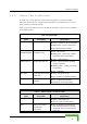
Menus and Parameters recommended to add a 2 dB safety margin to compensate for possible measurement inaccuracy or variance in the link quality. NOTE The SNR measurement at the AU is accurate only when receiving transmissions from the applicable SU. If necessary, use the Ping Test utility in the Site Survey menu to verify data transmission. When the Adaptive Modulation Algorithm is disabled, this parameter will serve to determine Fixed Modulation Level used for transmissions.
Chapter 4 - Operation and Administration The default is the highest supported Modulation Level. Table 4-11: Recommended Maximum Modulation Level* SNR Maximum Modulation Level SNR > 23 dB 8 21 dB < SNR < 23 dB 7 16 dB < SNR < 21 dB 6 13 dB < SNR < 16 dB 5 10 dB < SNR < 13 dB 4 8 dB < SNR < 10 dB 3 7 dB < SNR < 8 dB 2 6 dB < SNR < 7 dB 1 * The maximum supported value depends on the unit’s HW revision and on the Max Modulation Level according to the Sub-Band. 4.2.6.5.
Menus and Parameters 4.2.6.5.7 Number of HW Retries The Number of HW Retries parameter defines the maximum number of times that an unacknowledged packet is retransmitted. When the Adaptive Modulation Algorithm is disabled, a frame will be dropped when the number of unsuccessful retransmissions reaches this value. For details on the effect of this parameter when the Adaptive Modulation Algorithm is enabled, refer to section 4.2.6.5.9.
Chapter 4 - Operation and Administration 4.2.6.5.8.2 Burst Mode Time Interval The Burst Mode Time Interval defines the burst size, which is the time in which data frames are sent immediately without contending for the wireless medium. The range is 1 to the value of the Maximum Burst Duration defined for the SubBand. The default is 5 milliseconds or the value of Maximum Burst Duration defined for the Sub-Band (the lower of the two values). 4.2.6.5.