
User Manual

Chapter 4 - Operation and Administration of the Micro BTS BS Menu
4Motion 719 System Manual
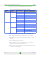
The value of Y that sets the upper limit for the Minimum and Maximum Size
parameters depends on the Maximum Cell Radius and Total Uplink Duration
parameters, using the following formula:
Y=A-3*(Total Uplink Duration)-(Extra TTG),
where A=46 for BW of 5 or 10 MHz, and 32 for BW of 7 MHz.
4.7.2.2.3.5 Maximum Map Size
Limits the maximum size of maps (in slots).
The available options are 10, 20 ...300 (10xN where N=1-30) or No Limitation. The
default is No Limitation.
4.7.2.2.4 Uplink Feedback Zone
The Uplink Feedback Zone menu enables viewing/updating the values configured
for the following parameter:
4.7.2.2.4.1 Permutation Base
The permutation base used in the uplink feedback zone.
The valid range is from 0 to 69.
4.7.2.2.5 Frame Structure Mode
The Frame Structure Mode menu enables viewing/updating the values configured
for the following parameter:
4.7.2.2.5.1 RCID Usage
Each transmitted MAP includes allocations for each MS it served, using the MS’s
CID for identifying each MS. The original CID includes 16 bits, which is
significantly more than practically needed since a maximum of 500 MSs can be
served by each BS. To reduce overhead, a smaller number of bits can be used,
based on RCID (Reduced CID) defined in the standard. This mechanism can be
Table 4-3: Calculating the Upper Limit Value (Y) for Minimum and Maximum Size
Bandwidth (MHz) Maximum Cell Radius Total Uplink Duration (slots) Extra TTG (symbols)
5/10 1, 2, 4, 8 4, 6 0
1, 2, 4, 8, 15, 23 5, 7 1
15, 23, 30 4, 6 2
30 5, 7 3
7 1, 2, 4, 8, 15, 23 4 0
1, 2, 4, 8, 15, 23, 30 3, 5 1
30 4 2