
User's Manual

Verifying Correct Operation
Base Station Equipment Installation Manual 24 BreezeACCESS Series
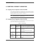
4. VERIFYING CORRECT OPERATION
4.1 Verifying Correct Operation of the AU-A/E-BS
After completing the installation as described above, the system starts operation.
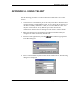
To verify correct operation, view the LED indicators located on the front panel of
the BS-AU modules as shown in Table 2-2 on page 13.
Note:
If the Access Units are not synchronized, reset the Master BS-AU unit and
then the Slave units to re-synchronize them.
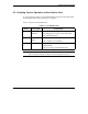
4.2 Verifying Correct Operation of the AU-A/E-NI
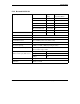
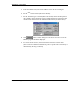
To verify proper operation, view the LED indicators located on the front and rear
panels of the AU-NI unit as described in Table 4-1.
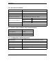
Table 4-1. AU-NI LEDs
Name Description Functionality
PWR Power Supply
12VDC
On – 12VDC power is supplied to the AU-NI
Off –Power is not supplied to the AU-NI
WLNK Wireless link
activity
Blinking –Receiving packet from the
wireless link
Off – No reception of packets from the
wireless link
ETH connector
embedded
(green) LED
Ethernet
activity
On – Receive/transmit on Ethernet port
Off – No receive/transmit on Ethernet port
ETH connector
embedded
(orange) LED
Ethernet
integrity
On – Unit is connected to Ethernet segment
Off – Unit is not connected to Ethernet
segment