BreezeMAX® PRO 5000 CPE Product Manual Software Version 1.
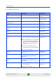
Document History Document History Topic Description Date Issued First Release New Product Manual SW Version 4.6, July 2009 Ethernet CS display Updated the Service Parameters page SW Version x.x, September 2009 New IDU power supply unit XTRM-SU-IDU-1D Added specifications and information SW Version 1.2, October 2009 “Service Parameters” on page 79 Removed the Modify option SW Version 1.2, October 2009 “User Registration” on page 60 Added EAP-AKA to the screen SW Version 1.
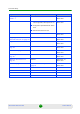
Document History Topic Description Date Issued 5 GHz Integral Antenna in 15°AZ x 15°EL instead of 20° SW Version 1.5, March 2010 Allocation of IP parameters: Removed SW Version 1.5, March 2010 Table 1-1 Table 1-5 LAN-Configurable, added options 66, 67 Configuration Upload/Download: added TFTP Authentication: Removed TLS TM/PM Files Control Removed SW Version 1.5, March 2010 “Aligning the PRO CPE’s External Antenna” on page 39 New section SW Version 1.
Legal Rights Legal Rights © Copyright 2010 Alvarion Ltd. All rights reserved. The material contained herein is proprietary, privileged, and confidential and owned by Alvarion or its third party licensors. No disclosure thereof shall be made to third parties without the express written permission of Alvarion Ltd. Alvarion Ltd. reserves the right to alter the equipment specifications and descriptions in this publication without prior notice.
Legal Rights (b) With respect to the Firmware, Alvarion warrants the correct functionality according to the attached documentation, for a period of fourteen (14) month from invoice date (the "Warranty Period")". During the Warranty Period, Alvarion may release to its Customers firmware updates, which include additional performance improvements and/or bug fixes, upon availability (the "Warranty"). Bug fixes, temporary patches and/or workarounds may be supplied as Firmware updates.
Legal Rights FULLEST EXTENT ALLOWED BY LAW, THE WARRANTIES AND REMEDIES SET FORTH IN THIS AGREEMENT ARE EXCLUSIVE AND IN LIEU OF ALL OTHER WARRANTIES OR CONDITIONS, EXPRESS OR IMPLIED, EITHER IN FACT OR BY OPERATION OF LAW, STATUTORY OR OTHERWISE, INCLUDING BUT NOT LIMITED TO WARRANTIES, TERMS OR CONDITIONS OF MERCHANTABILITY, FITNESS FOR A PARTICULAR PURPOSE, SATISFACTORY QUALITY, CORRESPONDENCE WITH DESCRIPTION, NON-INFRINGEMENT, AND ACCURACY OF INFORMATION GENERATED.
Legal Rights Indoor CPE - To comply with FCC RF exposure requirements in Section 1.1307and 2.1091 of FCC Rules, the antenna used for this transmitter must be kept at a separation distance of at least 20 cm from all persons and must not be co-located or operating in conjunction with any other antenna or transmitter. Outdoor CPE - To comply with FCC RF exposure requirements in Section 1.1307 and 2.
Legal Rights static charges. In any event, Alvarion is not liable for any injury, damage or regulation violations associated with or caused by installation, grounding or lightning protection. Disposal of Electronic and Electrical Waste Disposal of Electronic and Electrical Waste Pursuant to the WEEE EU Directive electronic and electrical waste must not be disposed of with unsorted waste. Please contact your local recycling authority for disposal of this product.
Important Notice Important Notice This user manual is delivered subject to the following conditions and restrictions: This manual contains proprietary information belonging to Alvarion Ltd. Such information is supplied solely for the purpose of assisting properly authorized users of the respective Alvarion products.
About This Manual About This Manual This document describes and explains how to install and manage the BreezeMAX PRO 5000 CPE units. This document contains the following chapters: Chapter 1 - Product description: Describes the PRO 5000 CPE, and its specifications. Chapter 2 - Installation: Describes how to install the PRO 5000 CPE. Chapter 3 - Commissioning: Describes how to configure basic parameters, align the antenna and validate unit operation.
Contents Contents Chapter 1 - Product Description.............................................................. 1 1.1 Introducing BreezeMAX PRO 5000 CPEs.................................................................3 1.1.1 General ...............................................................................................................3 1.1.2 Hardware Description..........................................................................................3 1.2 Specifications ...........................
Contents Chapter 3 - Commissioning ................................................................... 29 3.1 Commissioning Steps..............................................................................................31 3.2 Configuring Basic Parameters................................................................................32 3.2.1 The Basic Parameters.......................................................................................32 3.2.2 Configuration Tools ............................
Contents 4.8.3 Antenna Selection .............................................................................................71 4.9 ATPC Parameters .....................................................................................................72 4.9.1 Show .................................................................................................................72 4.9.2 ATPC.................................................................................................................73 4.
Figures Figures Figure 1-1: CPE Outdoor Units ................................................................................................ 4 Figure 1-2: Indoor Units............................................................................................................ 4 Figure 1-3: SU Alignment Unit (SAU) ....................................................................................... 4 Figure 2-1: ODU Pole Installation Using the Special Clamp, Arrow Facing Upwards ............
Figures Figure 4-12: Frequency Scanning Page................................................................................... 69 Figure 4-13: Antenna Selection Page ...................................................................................... 71 Figure 4-14: ATPC Show Page ................................................................................................ 72 Figure 4-15: Multi rate and ATPC Parameters Page................................................................
Tables Tables Table 1-1: Radio Specifications..................................................................................................... 5 Table 1-2: Sensitivity ..................................................................................................................... 6 Table 1-3: ODU/ODU Communication .......................................................................................... 6 Table 1-4: Data Communication (Ethernet Port) ...............................................
Tables Table 4-3: CPE Parameters Summary........................................................................................
Chapter 1 Product Description
Chapter 1 - Product Description In This Chapter: “Introducing BreezeMAX PRO 5000 CPEs” on page 3 “Specifications” on page 5 BreezeMAX PRO 5000 CPE 2 Product Manual
Chapter 1 - Product Description Introducing BreezeMAX PRO 5000 CPEs 1.1 Introducing BreezeMAX PRO 5000 CPEs 1.1.1 General The WiMAX-compatible BreezeMAX PRO 5000 CPE Subscriber Units (SUs) are powered by Sequans chipset. BreezeMAX PRO 5000 CPE is currently available in the 5 GHz frequency band, 1 Data. Differentiation between models of this product is based on its description: XTRM-SU-OD-1D-4.
Chapter 1 - Product Description Introducing BreezeMAX PRO 5000 CPEs Figure 1-1: CPE Outdoor Units The indoor unit is powered from the mains and connects to the ODU via a Category 5E Ethernet cable carrying the Ethernet data between the two units, as well as power (-54 VDC) and control signals to the ODU and status indications from the ODU.
Chapter 1 - Product Description Specifications 1.2 Specifications 1.2.1 Radio Table 1-1: Radio Specifications Item Details Frequency Band Frequencies (MHz) 5 GHz 4900-5950 Operation Mode TDD, Half Duplex Channel Bandwidth 5 MHz 10 MHz Central Frequency Resolution 0.125 MHz 5 GHz Integral Antenna Embedded dual polarization antenna, 16dBi, 15°AZ x 15°EL Antenna Port (units with external antenna) N-Type, 50 Ohm 5 GHz Detached Antennasa UNI-23-9: 23 dBi, 5.150-5.
Chapter 1 - Product Description 1.2.2 Specifications Sensitivity Table 1-2: Sensitivity 1.2.3 Modulation & Coding Sensitivity (dBm) @ 5 MHz BW Sensitivity (dBm) @ 10 MHz BW QPSK 1/2 -96 -93 QPSK 3/4 -93 -90 16QAM 1/2 -89 -86 16QAM 3/4 -86 -83 64QAM 2/3 -81 -78 64QAM 3/4 -80 -77 64QAM 5/6 -79 -76 IDU/ODU Communication Table 1-3: ODU/ODU Communication Item Details Cable Type Category 5E, Outdoor Data Cable, Double Jacket, 4x2x24# FTP Maximum Length 90 meter 1.2.
Chapter 1 - Product Description 1.2.5 Specifications Configuration and Management Table 1-5: Configuration and Management Item Description Management options Web-based (HTTP/HTTPS) TR-069 TFTP Management access From Wired LAN, Wireless Link Management access protection Access Password Allocation of IP parameters WAN - DHCP, options 43, 60, 66, 67 Software upgrade HTTP/TFTP Configuration Upload/Download HTTP/TFTP Authentication TTLS 1.2.6 Environmental 1.2.6.
Chapter 1 - Product Description Specifications Table 1-7: Environmental Specifications (Continued) Item Details Random Vibration IEC 68-2-64 Shock IEC-68-2-29 Salt Fog IEC-68-2-11 Ice Loading 25mm radial ice density 7kN/m3 Solar Radiation IEC-68-2-5, MIL-STD-810D Wind Speed 160Km/Hr required for antenna stability under operation 1.2.
Chapter 1 - Product Description Specifications 1.2.8 Physical and Electrical 1.2.8.1 Mechanical Table 1-9: Mechanical Specifications Unit Dimensions (mm) Weight (kg) CPE-IDU 156mm (L) X 60mm (W) X 33mm (T) or 0.3 95mm(L) X 57mm (W) X 32mm (T) 0.2 CPE-ODU-PRO-SA 230mm (H) X 230mm (W) X 63mm (T) 2 CPE-ODU-PRO-SE 230mm (H) X 260mm (W) X 73mm (T) 2 1.2.8.2 Electrical Table 1-10: Electrical Specifications Item Details Power Consumption 16.
Chapter 2 Installation
Chapter 2 - Installation In This Chapter: “Installing the ODU of the CPE” on page 12 “Installing the IDU-1D Indoor Unit of the CPE” on page 23 BreezeMAX PRO 5000 CPE 11 Product Manual
Chapter 2 - Installation 2.1 Installing the ODU of the CPE Installing the ODU of the CPE The following sections describe how to install the outdoor unit (ODU) of the PRO CPE. CPE operation is exclusive for point to point and requires professional installation. CAUTION ONLY experienced installation professionals who are familiar with local building and safety codes and, wherever applicable, are licensed by the appropriate government regulatory authorities should install outdoor units and antennas.
Chapter 2 - Installation 2.1.1.2 Installing the ODU of the CPE Additional Installation Requirements The following items are also required to install the ODU: Double shielded Cat.5E outdoor ethernet cable with two RJ-45 connectors* (90m) (see Section 2.1.3 for details on approved cables and maximum length), and an RJ-45 connectors crimping tool. For units that connect to external antenna: Antenna(s)* and RF cable* for connecting the antenna to the ODU.
Chapter 2 - Installation Installing the ODU of the CPE In some cases it might be necessary to up/down-tilt the antenna. An optional Tilt accessory for the ODU providing a tilt range of ±15° is available. The tilt option may be necessary to either improve the link conditions or, if the SU is too close to the BTS, to reduce the receive signals strength.
Chapter 2 - Installation Installing the ODU of the CPE Table 2-1: Approved Category 5E Ethernet Cables Manufacturer Part Number Southbay Holdings Limited 11th Fl., 15, Lane 347, Jong Jeng Rd. Shin Juang City, Taipei County Taiwan, R.O.C. Attn: Eva Lin Tel. 886-2-2832 3339 Fax. 886-2-2206 0081 E-mail: eva@south-bay.com.tw TSM2404A0D GU-Tech., LLC . - A Member of OVIS GroupTel/Fax : 732 918 8221 Mobile: 718 909 4093 www.OVIS.COM.TW www.GU-TECH.
Chapter 2 - Installation Installing the ODU of the CPE NOTE There is a groove on one end of the threaded rod. Insert the rods with the grooves pointing outward, and fasten them to the unit using a screwdriver. Install the unit with the bottom panel, which includes the connectors, facing downward. You can install the ODU with the arrow on the back of the unit facing upwards or rightwards. Match the polarity of the transmission antenna to the polarity of the receiver antenna.
Chapter 2 - Installation Installing the ODU of the CPE Figure 2-2: ODU Pole Installation Using the Special Clamp, Arrow Facing Rightwards BreezeMAX PRO 5000 CPE 17 Product Manual
Chapter 2 - Installation 2.1.4.2 Installing the ODU of the CPE Pole Mounting the ODU with the Tilt Accessory Figure 2-3: ODU Pole Installation Using the Tilt Accessory, Vertical Polarization To mount the ODU on a pole using the Tilt accessory: 1 Attach the Tilt accessory to the ODU using the two pairs of flat washers, spring washers and nuts supplied in the Tilt kit. 2 Mount the Tilt accessory on a 1" to 4" pole using two 9/16" metal bands.
Chapter 2 - Installation 2.1.5 Installing the ODU of the CPE Connectors SAU Port IDU COM Figure 2-4: Bottom Panel of the ODU (SA/SE model without sealing covers) 1 2 Figure 2-5: Top Panel of the ODU (SE model) Table 2-2: CPE-ODU-PRO Connectors Name Connector Functionality IDU COM 10/100Base-T (RJ-45) Connection to the IDU SAU Special mini USB Connection to SAU N-Type jack, 50 Ohm Connection to an external antenna (ANT, only in SE model) x2 2.1.6 Connecting the Cables 2.1.6.
Chapter 2 - Installation 2 Installing the ODU of the CPE Connect the other end of the grounding cable to a good ground (earth) connection. 2.1.6.2 Connecting the IDU-ODU Cable CAUTION Use only Category 5E 4x2x24# FTP outdoor cables from an approved manufacturer. See list of approved cables in Table 2-1.The length of the Indoor-to-Outdoor cable should not exceed 90 meters.
Chapter 2 - Installation Installing the ODU of the CPE Figure 2-6: Ethernet Connector Pin Assignments Data pairs are 1&2, 3&6. Power pair (proprietary solution) is 4&5.
Chapter 2 - Installation Installing the ODU of the CPE 2 Insert the cable with the assembled connector through the sealing nut. 3 To expose the groove, lightly squeeze the seal. Carefully insert the cable through the groove. 4 Insert the cable through the housing and insert the seal at the back end of the housing. 5 Tighten the sealing nut onto the housing. 6 Stricken the gasket on the front end of the housing.
Chapter 2 - Installation Installing the IDU-1D Indoor Unit of the CPE 2.2 Installing the IDU-1D Indoor Unit of the CPE 2.2.1 Installation Requirements 2.2.1.1 Packing List BMAX-CPE-IDU-1D or XTRM-SU-IDU-1D Wall mounting kit 2.2.1.2 Additional Installation Requirements Ethernet cable(s): a crossed cable if connecting to a hub/switch and a straight cable if connecting directly to a PC Network Interface Card (NIC).
Chapter 2 - Installation Installing the IDU-1D Indoor Unit of the CPE 2.2.3 IDU Connectors and LEDs 2.2.3.
Chapter 2 - Installation Installing the IDU-1D Indoor Unit of the CPE Table 2-4: CPE-IDU-1D Connectors Name Connector Functionality RADIO (on the front panel) 10/100Base-T (RJ-45) Connection to the ODU POWER (on the bottom panel) 3-pin AC Mains power connection Table 2-5: CPE-IDU-1D LEDs Name Description Functionality POWER (3) Power Indication Off - IDU is not powered or power failed Green - IDU power is OK ETH (2) Ethernet link status (Ethernet integrity) Off - No Ethernet conne
Chapter 2 - Installation 2.2.3.
Chapter 2 - Installation 2 Installing the IDU-1D Indoor Unit of the CPE Connect the IDU-ODU cable to the RADIO/LAN+DC connector (See Figure 2-8 and Figure 2-10). CAUTION Do not connect the data equipment to the RADIO/LAN+DC port. The RADIO/LAN+DC port supplies DC power to the ODU, and this may harm other equipment connected to it. 3 Connect the power cord to the unit's AC socket, located on the rear panel.
Chapter 2 - Installation 8 2.2.5 Installing the IDU-1D Indoor Unit of the CPE Verify proper operation as described in the applicable section of Chapter 3. Grounding the ODU-IDU Cable Follow the instructions below to ground the ODU-IDU cable. The following paragraphs describe one method for grounding the outdoor-rated Category 5E Ethernet cable through its drain wire. The actual connection method employed is left to the professional installer.
Chapter 3 Commissioning
Chapter 3 - Commissioning In This Chapter: “Commissioning Steps” on page 31 “Configuring Basic Parameters” on page 32 “Aligning the PRO CPE’s Internal Antenna” on page 35 “Operation Verification” on page 40 BreezeMAX PRO 5000 CPE 30 Product Manual
Chapter 3 - Commissioning 3.1 Commissioning Steps Commissioning Steps After completing the installation process, as described in the preceding chapter, several actions should be performed to ensure connectivity with a BTS and provisioning of services. After the CPE is connected with a BTS, it can be fully managed via the wireless link: 1 The basic parameters must be configured to ensure that the unit operates correctly and can communicate with a BTS.
Chapter 3 - Commissioning Configuring Basic Parameters 3.2 Configuring Basic Parameters 3.2.1 The Basic Parameters Table 3-1: CPE Basic Parameters Parameter Default Value Comment Country Code Ethernet Port auto Negotiation Enable/Disable Must be set in accordance to designated country and deployment scenario Enabled Ethernet Port Speed and Duplex Applicable only if Ethernet Auto Negotiation Enable/Disable is set to Disable User Name CPEMACaddress@WiMax.
Chapter 3 - Commissioning Configuring Basic Parameters NOTE Most parameters are changed to their new values only after reset (refer to Section 4.14 for more details). Once the basic parameters are configured, the unit should be reset in order to activate the new configuration. 3.2.2 Configuration Tools The CPEs include a Web Configuration Server, providing a web-based GUI for local configuration and monitoring. The Web Configuration Server can be accessed using a PC/Notebook with a web browser.
Chapter 3 - Commissioning Configuring Basic Parameters Figure 3-1: Login Window 4 The Main window of the Web Configuration Server is displayed, enabling access to the required parameters configuration and performance monitoring options. Refer to Chapter 4 for instructions on using the Web Configuration Server and detailed information on the various parameters and other features supported. 5 Configure the basic parameters listed in Table 3-1.
Chapter 3 - Commissioning Aligning the PRO CPE’s Internal Antenna 3.3 Aligning the PRO CPE’s Internal Antenna 3.3.1 SU Alignment Unit (SAU) The miniature SU Alignment Unit can be used during installation and testing to support an easy process of antenna alignment and provide the ODU's status indications. To connect the SAU to the ODU: 1 Remove the sealing cap of the ODU's SAU connector. 2 Connect the cable attached to the SAU to the SAU connector.
Chapter 3 - Commissioning Aligning the PRO CPE’s Internal Antenna Table 3-2: SAU LEDs Name Description Functionality AL Alarm indication Off - ODU is OK, diagnostic test passed Red - ODU failure PW Off - ODU is not powered or 3.
Chapter 3 - Commissioning Aligning the PRO CPE’s Internal Antenna Table 3-3: SAU LINK QUALITY LEDs Functionality (Continued) Bar LEDs SNR LEDs 2-10 (green) and 9 (red) are On RSSI -21dBm (saturation) LEDs 2-10 Blinking one after the other During full frequency scan LEDs 2-10 Blinking as follows: LED 6 lights, after 200ms LEDs 7 & 5 light, after 200ms LEDs 8 & 4 light, after 200ms LEDs 9 & 3 light, after 200ms LEDs 10 & 2 light, after 200ms all the LEDs are extinguished and then the sequence is rep
Chapter 3 - Commissioning 5 Aligning the PRO CPE’s Internal Antenna Rotate (and/or tilt if applicable) the ODU until the maximum link quality reading is achieved. If you encounter prolonged difficulty in achieving the expected link quality, try to improve the reception quality by placing the ODU at a higher point or in an alternate location. NOTE Ensure that the front of the antenna is always facing the BTS.
Chapter 3 - Commissioning 3.4 Aligning the PRO CPE’s External Antenna Aligning the PRO CPE’s External Antenna In order to achieve better link quality in units with external antenna, use the following steps to align the external antenna rather than the CPE itself. To align the external antenna: 1 Verify that the the unit is synchronized with a Base Station and ensure that all parameters are configured properly.
Chapter 3 - Commissioning 3.5 Operation Verification Operation Verification To verify proper operation of the PRO CPE, examine the LED indicators on the IDU (see Table 2-5) and the SAU (see Table 3-2). NOTE Verifying the correct operation of the ODU using the SAU LEDs is meaningful only after the configuration and alignment processes are completed, and the unit is synchronized with a BS.
Chapter 4 Operation
Chapter 4 - Operation In This Chapter: “Introduction to CPE Management” on page 43 “Accessing the Web Configuration Server” on page 44 “Using the Web Configuration Server” on page 45 “Show All” on page 46 “Unit Control Parameters” on page 47 “Registration Parameters” on page 59 “BST/AU Parameters” on page 63 “Radio Parameters” on page 67 “ATPC Parameters” on page 72 “Performance Monitor” on page 76 “Service Parameters” on page 79 “Management Parameters” on page 82 “Logout” on page
Chapter 4 - Operation 4.1 Introduction to CPE Management Introduction to CPE Management The units support the TR-069 CPE WAN Management Protocol (CWMP), allowing efficient management by an Auto Configuration Server (ACS). In addition, configuration and performance monitoring of a single unit can be performed either locally (via the Ethernet port) or remotely using any of the following options: Using a PC/Notebook with an http browser to access the built-in web configuration server.
Chapter 4 - Operation 4.2 Accessing the Web Configuration Server Accessing the Web Configuration Server To configure parameters using the Web Configuration Server, connect a PC/Notebook with a web browser to the Ethernet port of the IDU, using a straight Ethernet cable. 1 Configure the PC's IP parameters to enable connectivity with the unit. The IP address of the CPE for local management access is 192.168.254.251. The Subnet Mask is 255.255.255.0. The recommended IP address for the PC is 192.168.254.
Chapter 4 - Operation 4.3 Using the Web Configuration Server Using the Web Configuration Server The Web Configuration Server view when using a Notebook/PC consists of a number of menu links (to the left). Clicking on each of them will display the configuration/status page for the selected menu item, with the applicable content (configurable parameters/options or status information) in the main area.
Chapter 4 - Operation 4.4 Show All Show All The Show All page enables viewing all the configurable parameters of the unit. In addition, the displayed information includes the general hardware and software properties of the units and relevant status details. The display includes all the items available upon selecting the Show option for specific groups of parameters.
Chapter 4 - Operation 4.5 Unit Control Parameters Unit Control Parameters The Unit Control menu includes the following options: Show Reset Unit Change Password SW Versions Control Configuration Control Ethernet Operation (Op) Mode 4.5.
Chapter 4 - Operation Unit Control Parameters » RF Version: The version of the radio module. » CPE Interface Type: 1D (one data port) » Radio Type: the receive (Rx) and transmit (Tx) capacity of the radio. 1R/1T - one receive (Rx) and one transmit (Tx).
Chapter 4 - Operation Unit Control Parameters » Shadow SW Version » Running from: Main or Shadow Upload/Download Parameters: » Local TFTP Server IP address: the IP address of the TFTP server from the LAN side used for SW File/Configuration File download. » Remote TFTP Server IP address: the IP address of the TFTP server from the WAN side used for SW File/Configuration File download. » SW File Name: the name in the TFTP server of the SW version to be downloaded to the unit.
Chapter 4 - Operation 4.5.3 Unit Control Parameters Change Password Figure 4-3: Change Password Page The Change Password page enables to change the login password. Enter the old password, the new password and re-enter the new password for confirmation. Then click Save New Password. Click Refresh to clear the fields. NOTE Notify the administrator of the new password! Valid passwords: 1 to 20 printable characters, case sensitive.
Chapter 4 - Operation 4.5.4 Unit Control Parameters SW Versions Control Figure 4-4: SW Versions Control Page The CPE can contain two SW versions: Main: Normally, each time the CPE resets it will reboot using the version defined as Main. Shadow: Normally the Shadow version is the backup version. Each time a new SW File is downloaded to the CPE, it will be stored as a Shadow version, replacing the previous Shadow Version.
Chapter 4 - Operation Unit Control Parameters The CPE functions as a TFTP client, enabling the loading of SW files from a TFTP server. The SW Versions Control submenu includes the following fields: Main SW File Name: the name of the Main software file. Main SW Version: the version of the Main software. Shadow SW File Name: the name of the software file in the shadow. Shadow SW Version: the version of the software in the shadow.
Chapter 4 - Operation Unit Control Parameters If a different IP address is configured in the PC with the TFTP, configure the TFTP Server IP Address to the same address. 3 Enter the name of the SW file (as called in the TFTP server) as the SW File Name. 4 Select Perform SW Download and confirm the download request. Wait to receive a success/failure message. 5 Following a successful download, the loaded SW version becomes the Shadow version in the unit.
Chapter 4 - Operation Unit Control Parameters The Configuration Control submenu enables to define parameters related to uploading/downloading of configuration files to/from the CPE, and to initiate the upload/download operation. This submenu also enables downloading of a country codes file (always named country_codes.xml).
Chapter 4 - Operation 4 Unit Control Parameters Click Perform Action. Confirm the upload request and wait to receive a success/failure message. To perform configuration or country code file download: 1 Check that the required file is available in the TFTP Server directory in a PC connected to the unit. 2 Typically it is recommended to configure the IP address of the PC to 192.168.154.250, which is the default TFTP Server IP address of the unit.
Chapter 4 - Operation 4.5.6 Unit Control Parameters Licences Figure 4-6: License Control Page Licence control enables loading licence files and view the license parameters. By default the CPEs are limited from factory to 2 Mb capacity. You can increase the capacity to 6 Mb or to Unlimited by purchasing a license.
Chapter 4 - Operation Unit Control Parameters License Files: list of the valid license files that are loaded to the unit License Parameters: the Bandwidth accepted for the unit. In case of UNLIMITED the value is 0. The license files can also be uploaded using the TR069 option. The license can be downloaded to the CPE just by using the SW Upgrade procedure, only that the file pointed at is a *.lic file. Refer to “SW Versions Control” on page 51. 4.5.
Chapter 4 - Operation » Unit Control Parameters 100Mbps Full-Duplex Ethernet Down Timeout (applicable only in IP CS): Enables to configure Ethernet downtime, after which it will be up again. The range is from 3 seconds up to 100 seconds. Click Apply to save the changes.
Chapter 4 - Operation 4.6 Registration Parameters Registration Parameters The Registration menu includes the following sub-menus: Show User Registration 4.6.1 Show Select this submenu to view the registration parameters (excluding the User Password that is not shown for security reasons). Figure 4-8: Registration Show Page User Name (Configured and Current): the name of the unit, to be used for service provisioning. Changes to the User Name parameter are applied only after reset.
Chapter 4 - Operation Registration Parameters » Rejected: the CPE’s authentication request was rejected. » Authenticated: the CPE is connected to the BTS. » Not Operational: no BTS is found. Click Refresh to update the information. 4.6.2 User Registration Figure 4-9: User Registration Page The Registration page enables to set the following parameters. After setting the parameters, click Apply. The changes are saved, and the Registration - Show page is displayed.
Chapter 4 - Operation Registration Parameters The new password is applied only after rebooting the unit. Password Confirmation: re-enter the new password when defining one. Organization: enter the name of the organization (customer) using the unit. This parameter is optional, and is intended for optional use by the Network Management System. The Organization Name can include up to 32 printable characters. Address: use this field to enter the location of the unit.
Chapter 4 - Operation Registration Parameters mode and will complete the network entry without EAP-TTLS authentication process. The default is EAP-TTLS.
Chapter 4 - Operation 4.7 BST/AU Parameters BST/AU Parameters The quest for load sharing together with the desire to create best throughput conditions for the CPE created the need for the Best BS feature, to enable an CPE to connect to the best BS in its neighborhood. The CPE scans a set of frequencies (see “Radio Parameters” on page 67) searching for BSs it can communicate with. Each BS in the network is configured with a unique BS ID.
Chapter 4 - Operation BST/AU Parameters In case of loosing the link connection, the CPE will: » Wait 4 minutes if BS is preferred, or preferred mask is not set » Go directly to scanning if BS is not preferred and mask is set Figure 4-10: BST/AU Page The BST/AU page includes the following parameters: Best BST/AU Parameters and Best BST/AU Table: BreezeMAX PRO 5000 CPE 64 Product Manual
Chapter 4 - Operation » BST/AU Parameters Configured Best BS ID: the configured Preferred BST/AU ID. Together with the BS ID Mask, it is used to define the range of BSs that can communicate with the unit. The BS ID comprises 6 octets of up to 3 digits each, where the range of each group is 0 to 255. The default BS ID is 0.0.0.0.0.0 » Current Best BS ID » Selected Best BS ID » Preferred Best BS ID » Current Preferred BS ID If a BS ID is set on the preferred BS and the mask is 255.255.255.255.255.
Chapter 4 - Operation BST/AU Parameters » Rx Frequency (KHz) » SNR (dB) » RSSI (dBm) » Bandwidth BST/AU and Preferred BST/AU Parameters » BST/AU ID » BST/AU ID Mask » Preferred BST/AU ID » Preferred BST/AU ID Mask » Mobility Mode: enables defining the expected mobility of the CPE: Nomadic or Mobile. The default is Nomadic. After configuring the parameters, click Apply to save your changes. Preferred BS Loss - Timeout before trying to connect to a preferred BS.
Chapter 4 - Operation 4.8 Radio Parameters Radio Parameters The Radio Parameters page includes the following options: Show Frequency Scanning Antenna Selection 4.8.1 Show The Show page displays the Frequency and Bandwidth selected by the scanning mechanism. Figure 4-11: Radio - Show Page 4.8.2 Frequency Scanning The Frequency Scanning page enables viewing and updating the set of frequencies to be used during the scanning process.
Chapter 4 - Operation Radio Parameters The Intermediate Steps can be used to define additional frequencies using a finer resolution. The intermediate steps are defined as follows: NOTE In the current version, intermediate steps are disabled.
Chapter 4 - Operation Radio Parameters Figure 4-12: Frequency Scanning Page The Frequency Scanning menu includes the following fields: Scanning Table: displays the list of all current frequencies that participate in the full scanning process. Following the Full Scanning Table, the Best BS Scanning Table displays all the frequencies associated with BSs that are included in the current Best BS Table.
Chapter 4 - Operation Radio Parameters Start Rx Frequency (KHz): the lowest frequency in the range of frequencies to be scanned (in KHz). The available values depend on the radio band of the unit. End Rx Frequency (KHz): the highest frequency in the range of frequencies to be scanned (in KHz). The available values depend on the radio band of the unit.
Chapter 4 - Operation Radio Parameters Delete All Discrete Frequencies: to delete all discrete frequencies, click on Delete All. Discrete Scanning Frequencies: enables to enter discrete frequencies, as follows: » Update List of Discrete Frequencies: Enter a list of up to 10 discrete frequencies in steps of 2.5MHz, separated by commas (no space). This list will replace the current list of discrete frequencies.
Chapter 4 - Operation 4.9 ATPC Parameters ATPC Parameters In regular operation, the level of the signal transmitted by the CPE is controlled by the Adaptive Transmission Power Control (ATPC) mechanism of the serving BS. The ATPC page enable temporary control of the signal transmitted by the CPE. It is intended for test purposes only. These settings will not be saved and will automatically return to original values as received from the BS when the unit resets or upon closing the web interface.
Chapter 4 - Operation 4.9.2 ATPC Parameters ATPC Figure 4-15: Multi rate and ATPC Parameters Page From the ATPC page, you can enable/disable the ATPC mechanism and select your country code. 4.9.2.1 ATPC To enable/disable the ATPC mechanism: 1 Select Disable to temporarily disable ATPC for testing purposes. You will be prompted to enter the requested Tx Power. The available range depends on unit type/radio band.
Chapter 4 - Operation ATPC Parameters Selecting from a set of default country codes that appear in the ATPC window as described below. Uploading a country codes file as described in the Configuration Control (see “Configuration Control” on page 53. The Current Country Code Data field displays the country code that is currently used. After performing reset to the unit, the configured country code becomes the current country code.
Chapter 4 - Operation ATPC Parameters To select a country code: IMPORTANT The selected Country Code must comply with applicable local radio regulations. The selected Country Code may affect the maximum Tx power and also the system performance. Select the required country code from the list and reset the unit to apply the new country code.
Chapter 4 - Operation 4.10 Performance Monitor Performance Monitor The Performance Monitor Page enables viewing performance monitoring of link quality, and Ethernet counters, and enables to set the monitoring intervals. The CPE collects data on a regular basis and is able to deliver the data to the Access Control Server NMS (Network Management Station) upon request. The Performance Monitor menu includes the following options: Link Quality Counters Page Ethernet Counters 4.10.
Chapter 4 - Operation Performance Monitor CINRStd Reuse 1 (dB) CINR Reuse 3 (dB) CINRStd Reuse 3 (dB) RSSI RSSIStd Last Tx Power (dBm) UL Fec Code 4.10.2 Ethernet Counters The Ethernet On-Line Counters page displays RX and Tx levels for the Ethernet connection. Figure 4-17: Ethernet Counters Page The Ethernet On-Line Counters table displays a continuously updated list of the traffic counters. The display is updated every 2 seconds based on counters collected during this period.
Chapter 4 - Operation Performance Monitor Total Bytes Total Packets Rate counts are the average rate (Bytes/Packets per second) for the last measurement interval (2 seconds). Total counts are the accumulated number of Bytes/Packets since the last unit reset or the last Counters Reset.
Chapter 4 - Operation 4.11 Service Parameters Service Parameters The Service Parameters page enables viewing and setting the service related parameters configured via the BTS. To edit parameters, select the Change Service Parameters page. Figure 4-18: Service Page - IP CS Mode (Show Parameters) Figure 4-19: Change Service Parameters - Ethernet CS Mode NOTE The Operation mode cannot be modified from the Change Service Parameters page.
Chapter 4 - Operation Service Parameters Operation Mode: displays the convergence sublayer (CS) in the wireless access network: IP CS (DSCP based classification) or Ethernet CS (VLAN based classification). Service Definition table: displays the Service Rules to be used for handling the relevant classifiers (VLAN/DSCP) of packets processed by the units. For each service rule, the following parameters are displayed: » Service ID: up to 8 non-overlapping Service Rules can be defined via the BTS.
Chapter 4 - Operation Service Parameters For Ethernet CS mode: Access VLAN: From 0 to 4095 or 4096 (Transparent). Transparent is used to allow untagged packets. In the Change Service Parameters page, you can change the Access VLAN as required. Click Modify to apply the changes. Operation Mode: displays the convergence sublayer (CS) in the wireless access network: IP CS (DSCP based classification) or Ethernet CS (VLAN based classification). The operation mode is detected automatically.
Chapter 4 - Operation 4.12 Management Parameters Management Parameters The Management Page enables viewing the parameters related to remote (over the air) management of the device, and configure the parameters of the DHCP client. The Management Parameters menu includes the following options: Management Parameters DHCP Client Configuration 4.12.
Chapter 4 - Operation Management Parameters eCPE Manager IP Address (acquired from a DHCP server, or Not Available) eCPE Manager Connection Status (Up, Down or Not Connected) 4.12.2 DHCP Client Configuration Figure 4-21: Dhcp Client Configuration The DHCP Client Configuration page enables viewing and updating the parameters of the DHCP client.
Chapter 4 - Operation 4.13 Logout Logout To log out, click on the Logout menu. The following window is displayed: Figure 4-22: Logout Page Click on the Logout button. The Login page is displayed.
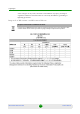
Chapter 4 - Operation 4.14 Parameters Summary Parameters Summary Table 4-3: CPE Parameters Summary Parameter Range Default Run-Time Updated Password Up to 20 printable characters, case sensitive installer No Local TFTP Server IP Address IP address 192.168.254.250 Yes Upload Upload No Unit Control Parameters Configuration Upload File Name Configuration Download File Name Choose Upload/Download Action Download Licences From 2 to Unlimited Licence.
Chapter 4 - Operation Parameters Summary Table 4-3: CPE Parameters Summary Parameter Range Default Country Up to 12 printable characters Authentication Not Authenticated Run-Time Updated Yes EAP TTLS Yes EAP TTLS BS ID Parameters BST/AU ID 6 octets of up to 3 digits each. Each group range is 0-255. 0.0.0.0.0.0 Yes BST/AU ID Mask 6 octets of up to 3 digits each. Each group range is 0-255. 0.0.0.0.0.0 Yes Preferred BST/AU ID 6 octets of up to 3 digits each. Each group range is 0-255.
Chapter 4 - Operation Parameters Summary Table 4-3: CPE Parameters Summary Parameter Range Default Run-Time Updated 0-63 6 No Management Configured DSCP Classifier BreezeMAX PRO 5000 CPE 87 Product Manual
Appendix A Troubleshooting
Appendix A - Troubleshooting In This Appendix: “CPE Troubleshooting” on page 90 BreezeMAX PRO 5000 CPE 89 Product Manual
Appendix A - Troubleshooting A.1 CPE Troubleshooting CPE Troubleshooting Refer to the BreezeMAX Troubleshooting Guide for additional information on troubleshooting. Problem and Indication Possible Cause Corrective Action Power Failure: None of the IDU LEDs illuminate after connecting to power Mains power problem Verify mains power availability on the power outlet to which the power supply is connected. Try using a different outlet.
Appendix A - Troubleshooting CPE Troubleshooting Problem and Indication Possible Cause Corrective Action The Ethernet Activity and/or Integrity LEDs are on, but no management access using Telnet or web browser, and the unit does not respond to ping. Wrong IP configuration Make sure that the PC is on the same subnet as the unit. The unit's IP address for management purposes is 192.168.254.251, and the subnet mask is 255.255.255.0.
Glossary
Glossary AAA Authentication, Authorization, and Accounting (pronounced "triple a."). A system (or several systems) that controls what resources users have access to, and keeps track of the activity of users over the network. ACS Auto Configuration Server. A CPE management system supporting secure auto-configuration as well as other CPE management functions. AES-CCM Advanced Encryption Standard - Counter mode with Cipher-block chaining Message authentication code.
Glossary CRC Cyclical Redundancy Check. A common technique for detecting data transmission errors, in which the frame recipient calculates a remainder by dividing frame contents by a prime binary divisor and compares the calculated remainder to a value stored in the frame by the sending equipment. CS Convergence Sublayer. Particular protocols that are responsible for gathering and formatting higher layer information so it can be processed by the lower layers.
Glossary FFT Fast Fourier Transform. An algorithm for converting data from the time domain to the frequency domain; often used in signal processing. FIPS Federal Information Processing Standards. The Federal Information Processing Standard (FIPS) Publication 140-2 1, called Security Requirements for Cryptographic Modules, is a United States security standard used to certify cryptographic modules. FTP File Transfer Protocol. A protocol for exchanging files over the Internet.
Glossary MCS Multipoint Communications Systems. Applications licensed at 2500 MHz in Canada. A wide variety of applications are possible including one-way and two-way transmission and a diversity of distribution capacities. MMDS Multichannel Multipoint Distribution Service. MMDS is a licensed wireless service that has the capability to provide broadband access. MMDS operates in several parts of the 2 GHz spectrum. MSCHAP Microsoft Challenge Handshake Authentication Protocol.
Glossary PPPoE Point-to-Point Protocol over Ethernet. PPPoE relies on two widely accepted standards: PPP and Ethernet. PPPoE is a specification for connecting the users on an Ethernet to the Internet through a common broadband medium, such as a single DSL line, wireless device or cable modem. All the users over the Ethernet share a common connection, so the Ethernet principles supporting multiple users in a LAN combines with the principles of PPP, which apply to serial connections.
Glossary SNMP Simple Network Management Protocol. A network management protocol that provides a means to monitor and control network devices, and to manage configurations, statistics collection, performance, and security. SNMP works by sending messages, called protocol data units (PDUs), to different parts of a network. SNMP-compliant devices, called agents, store data about themselves in Management Information Bases (MIBs) and return this data to the SNMP requesters. SNR Signal to Noise Ratio.
Glossary VoIP Voice over Internet Protocol. Provides an advanced digital communications network that bypasses the traditional public switched telephone system and uses the Internet to transmit voice communication. VoIP enables people to use the Internet as the transmission medium for telephone calls by sending voice data in packets using IP rather than by traditional circuit switched transmissions of the PSTN. WAN Wide Area Network. A computer network that spans a relatively large geographical area.