
User's Manual
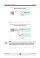
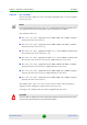

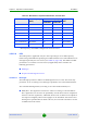


Table Of Contents
- BreezeMAX Extreme System Manual
- About This Manual
- Contents
- System Description
- 1.1 About WiMAX
- 1.2 WiMAX Network Architecture
- 1.3 BreezeMAX Extreme
- 1.4 Specifications
- Installation
- 2.1 BTS Installation
- 2.2 GPS Installation
- 2.3 Indoor Power Supply Installation
- 2.4 Cable Connections
- 2.5 External Antennas Connection
- Commissioning
- Operation and Administration
- 4.1 BreezeMAX Extreme System Management
- 4.2 The Monitor Program
- 4.3 IP Addresses Configuration
- 4.4 The Main Menu
- 4.5 BTS Menu
- 4.5.1 Show Summary
- 4.5.2 Show Properties
- 4.5.3 Configuration
- 4.5.4 Unit Control
- 4.5.4.1 Change Password
- 4.5.4.2 Reset BTS
- 4.5.4.3 Reset to BTS Factory Defaults
- 4.5.4.4 SW Version Control
- 4.5.4.5 Configuration File Control
- 4.5.4.6 Monitor Inactivity Timeout
- 4.5.5 Fault Management
- 4.5.6 Performance Counters
- 4.6 ASN-GW Menu
- 4.6.1 AAA
- 4.6.2 Services Menu
- 4.7 Sector Menu
- 4.8 BS Menu
- 4.9 Radio Channel Menu
- 4.10 Antenna Menu
- 4.11 GPS Menu
- 4.12 MS Menu
- 4.13 Parameters Summary
- Glossary

Chapter 4 - Operation and Administration BTS Menu
BreezeMAX Extreme 79 System Manual
* The frequency 5725 MHz is illegal and cannot be used.
4.5.3.5.8 DFS
The DFS option is applicable only for units operating in the 5 GHz frequency
bands using a Band Name specifying that DFS should be used. The DFS feature is
managed separately for each sector (see “DFS” on page 128). The BTS level DFS
parameters are common to both sectors (if applicable) and it includes the
following parameters:
DFS Type
Frequencies Management Level
4.5.3.5.8.1 DFS Type
The DFS Type parameter defines the DFS algorithm to be used. This read-only
parameter is set according to the DFS type specified in the selected Band Name.
The available DFS algorithm (according to the selected Band Name) are:
ETSI/FCC: The algorithm searches for radars according to relevant ETSI or
FCC regulations. To increase the probability of radar detection for compliance
with the relevant regulations, additional silence zone is added to the uplink at
the expense of slightly reduced throughput in the downlink. This means that
although the specified DL-UL Ratio is 60-40, the actual DL-UL Ratio is 40-60
in ETSI and 45-65 in FCC.
Table 4-3: Band Name’s Dependent Parameters, 5.4 GHz Units
Band Name Frequency Range
(MHz)
Maximum EIRP (dBm) Supported
DFS
5 MHz BW 10 MHz BW
5.4 GHz Universal 5470-5900* No Limit No Limit None
5.9 GHz Universal 5900-5950 No Limit No Limit None
5.4 GHz ETSI 5470-5725 27 30 ETSI
5.8 GHz ETSI 5725-5875 30 33 ETSI
5.4 GHz FCC 5470-5725 33 36 FCC
5.8 GHz FCC 5725-5875 33 36 None
5.4 - 5.8 GHz ETSI 5470-5875* 30 33 Normal ETSI
5.4 - 5.8 GHz FCC 5470-5875* 33 36 Normal FCC