
User's Manual
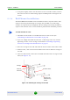

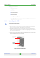

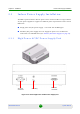


Table Of Contents
- BreezeMAX Extreme System Manual
- About This Manual
- Contents
- System Description
- 1.1 About WiMAX
- 1.2 WiMAX Network Architecture
- 1.3 BreezeMAX Extreme
- 1.4 Specifications
- Installation
- 2.1 BTS Installation
- 2.2 GPS Installation
- 2.3 Indoor Power Supply Installation
- 2.4 Cable Connections
- 2.5 External Antennas Connection
- Commissioning
- Operation and Administration
- 4.1 BreezeMAX Extreme System Management
- 4.2 The Monitor Program
- 4.3 IP Addresses Configuration
- 4.4 The Main Menu
- 4.5 BTS Menu
- 4.5.1 Show Summary
- 4.5.2 Show Properties
- 4.5.3 Configuration
- 4.5.4 Unit Control
- 4.5.4.1 Change Password
- 4.5.4.2 Reset BTS
- 4.5.4.3 Reset to BTS Factory Defaults
- 4.5.4.4 SW Version Control
- 4.5.4.5 Configuration File Control
- 4.5.4.6 Monitor Inactivity Timeout
- 4.5.5 Fault Management
- 4.5.6 Performance Counters
- 4.6 ASN-GW Menu
- 4.6.1 AAA
- 4.6.2 Services Menu
- 4.7 Sector Menu
- 4.8 BS Menu
- 4.9 Radio Channel Menu
- 4.10 Antenna Menu
- 4.11 GPS Menu
- 4.12 MS Menu
- 4.13 Parameters Summary
- Glossary

Chapter 2 - Installation Indoor Power Supply Installation
BreezeMAX Extreme 43 System Manual
1 Place the Power Supply on a table/shelf or use 4 screws to mount the unit to
the wall.
2 For cable connection, refer to “Cable Connection” on page 46.
2.3.2 PoE AC/DC Power Supply
A Universal Indoor Unit AC Power Adapter is used to supply DC power over the
Ethernet connection to 5 GHz BTS units. This is an AC to DC power transfer
device, which can provide a 70W single DC output with constant voltage source.
This unit can be wall mounted or placed on the desktop.
For cable connection, refer to “Cable Connection” on page 46
To install the indoor high power supply unit:
Figure 2-14: Low Power PoE AC/DC Power Supply