
User's Manual
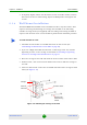

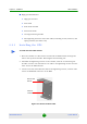

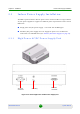


Table Of Contents
- BreezeMAX Extreme System Manual
- About This Manual
- Contents
- System Description
- 1.1 About WiMAX
- 1.2 WiMAX Network Architecture
- 1.3 BreezeMAX Extreme
- 1.4 Specifications
- Installation
- 2.1 BTS Installation
- 2.2 GPS Installation
- 2.3 Indoor Power Supply Installation
- 2.4 Cable Connections
- 2.5 External Antennas Connection
- Commissioning
- Operation and Administration
- 4.1 BreezeMAX Extreme System Management
- 4.2 The Monitor Program
- 4.3 IP Addresses Configuration
- 4.4 The Main Menu
- 4.5 BTS Menu
- 4.5.1 Show Summary
- 4.5.2 Show Properties
- 4.5.3 Configuration
- 4.5.4 Unit Control
- 4.5.4.1 Change Password
- 4.5.4.2 Reset BTS
- 4.5.4.3 Reset to BTS Factory Defaults
- 4.5.4.4 SW Version Control
- 4.5.4.5 Configuration File Control
- 4.5.4.6 Monitor Inactivity Timeout
- 4.5.5 Fault Management
- 4.5.6 Performance Counters
- 4.6 ASN-GW Menu
- 4.6.1 AAA
- 4.6.2 Services Menu
- 4.7 Sector Menu
- 4.8 BS Menu
- 4.9 Radio Channel Menu
- 4.10 Antenna Menu
- 4.11 GPS Menu
- 4.12 MS Menu
- 4.13 Parameters Summary
- Glossary

Chapter 2 - Installation GPS Installation
BreezeMAX Extreme 39 System Manual
High gain GPS Antenna
» High gain antenna
» 25m cable
» Pole mount bracket
» Two metal bands
» Carriage mounting bracket
» Two Lightning Arrestors with 0.5m cables, including screws, washers, and
spring washers (2 x UNC10-32)
2.2.3 Installing the GPS
1 Place the bracket on a flat surface and thread the GPS antenna through the
hole at the top of the bracket. Hand-tighten the fastening nut.
2 Assemble the lightening arrestor on the bracket, with the screws facing the
bracket. Connect one end of the 0.5 m cable to the lightening arrestor and the
other end to the GPS antenna.
3 Connect one end of the GPS 3m cable to the lightening arrestor, and the other
end to the GPS ANT connector on the BTS.
To install the basic GPS antenna:
Figure 2-11: Bracket for Basic GPS
Hole for GPS
antenna
Holes for
metal bands