
User's Manual
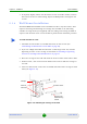

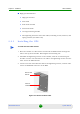

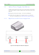


Table Of Contents
- BreezeMAX Extreme System Manual
- About This Manual
- Contents
- System Description
- 1.1 About WiMAX
- 1.2 WiMAX Network Architecture
- 1.3 BreezeMAX Extreme
- 1.4 Specifications
- Installation
- 2.1 BTS Installation
- 2.2 GPS Installation
- 2.3 Indoor Power Supply Installation
- 2.4 Cable Connections
- 2.5 External Antennas Connection
- Commissioning
- Operation and Administration
- 4.1 BreezeMAX Extreme System Management
- 4.2 The Monitor Program
- 4.3 IP Addresses Configuration
- 4.4 The Main Menu
- 4.5 BTS Menu
- 4.5.1 Show Summary
- 4.5.2 Show Properties
- 4.5.3 Configuration
- 4.5.4 Unit Control
- 4.5.4.1 Change Password
- 4.5.4.2 Reset BTS
- 4.5.4.3 Reset to BTS Factory Defaults
- 4.5.4.4 SW Version Control
- 4.5.4.5 Configuration File Control
- 4.5.4.6 Monitor Inactivity Timeout
- 4.5.5 Fault Management
- 4.5.6 Performance Counters
- 4.6 ASN-GW Menu
- 4.6.1 AAA
- 4.6.2 Services Menu
- 4.7 Sector Menu
- 4.8 BS Menu
- 4.9 Radio Channel Menu
- 4.10 Antenna Menu
- 4.11 GPS Menu
- 4.12 MS Menu
- 4.13 Parameters Summary
- Glossary

Chapter 2 - Installation BTS Installation
BreezeMAX Extreme 36 System Manual
3 If required, slightly release the tilt bracket screws to enable rotation, and the
Tilt Control screws to enable tilting; Adjust the BTS position and tighten the
screws.
2.1.6 Wall Mount Installation
The BreezeMAX Extreme BTS can be installed on walls or any flat surface. This
requires attaching and fastening the carriage with the BTS to the wall using
suitable securing means (not supplied) and then tilting and rotating the BTS as
required. The location of the screws should be planned with maximum precision.
1 Assemble the tilt bracket on the BTS and fasten its four screws (see
“Assembling the Tilt Bracket on the BTS” on page 29).
2 If you use a High-Gain GPS antenna with a cable longer than 3m, install a
lightening arrestor on the carriage as described in “Installing a Lightening
Arrestor for the High-Gain GPS Antenna” on page 31.
3 Place the carriage on the wall and mark the exact location of the holes to drill.
4 Drill the holes, and use four metal dowels and screws to affix the carriage to
the wall.
5 Insert the Tilt Control screws into the middle-side hole of the carriage on both
sides (see Figure 2-10).
To install the BTS on a wall:
Figure 2-10: Mounting the Carriage on the Wall
Carriage
Till control screw
Holes for
wallmount
screws (to be
fastened using
dowels