
User's Manual
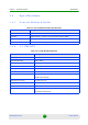
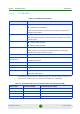


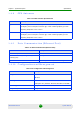
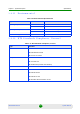
Table Of Contents
- BreezeMAX Extreme System Manual
- About This Manual
- Contents
- System Description
- 1.1 About WiMAX
- 1.2 WiMAX Network Architecture
- 1.3 BreezeMAX Extreme
- 1.4 Specifications
- Installation
- 2.1 BTS Installation
- 2.2 GPS Installation
- 2.3 Indoor Power Supply Installation
- 2.4 Cable Connections
- 2.5 External Antennas Connection
- Commissioning
- Operation and Administration
- 4.1 BreezeMAX Extreme System Management
- 4.2 The Monitor Program
- 4.3 IP Addresses Configuration
- 4.4 The Main Menu
- 4.5 BTS Menu
- 4.5.1 Show Summary
- 4.5.2 Show Properties
- 4.5.3 Configuration
- 4.5.4 Unit Control
- 4.5.4.1 Change Password
- 4.5.4.2 Reset BTS
- 4.5.4.3 Reset to BTS Factory Defaults
- 4.5.4.4 SW Version Control
- 4.5.4.5 Configuration File Control
- 4.5.4.6 Monitor Inactivity Timeout
- 4.5.5 Fault Management
- 4.5.6 Performance Counters
- 4.6 ASN-GW Menu
- 4.6.1 AAA
- 4.6.2 Services Menu
- 4.7 Sector Menu
- 4.8 BS Menu
- 4.9 Radio Channel Menu
- 4.10 Antenna Menu
- 4.11 GPS Menu
- 4.12 MS Menu
- 4.13 Parameters Summary
- Glossary

Chapter 1 - System Description Specifications
BreezeMAX Extreme 18 System Manual
The following table shows the transmitter power level at the antenna connector as
a function of antenna type in 5.8 GHz BTS.
Internal, 15.5dbi 1RF chain /5MHz 8.5
Internal, 15.5dbi 2RF chains/5MHz 8.5
Internal, 15.5dbi 1RF chain /10MHz 11.5
Internal, 15.5dbi 2RF chains/10MHz 11.5
Omni, 8dbi 1RF chain /5MHz 16.7
Omni, 8dbi 2RF chains/5MHz 13.7
Omni, 8dbi 1RF chain /10MHz 19.7
Omni, 8dbi 2RF chains/10MHz 16.7
Table 1-5: Transmitter Power Level per Antenna Gain
Antenna type and gain Transmitter power (dbm)
Internal , dual slant 15.5dbi 20.5
Omni, 9.5dbi 24.2
Sectorial 17dbi 19.7
Table 1-4: Transmitter Power Level per Antenna Gain and Channel Bandwidth
Antenna type RF chains/CH BW Transmitted power (dbm)