
User's Manual
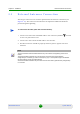
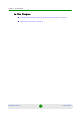
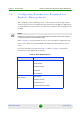
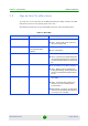
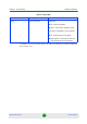
Table Of Contents
- BreezeMAX Extreme System Manual
- About This Manual
- Contents
- System Description
- 1.1 About WiMAX
- 1.2 WiMAX Network Architecture
- 1.3 BreezeMAX Extreme
- 1.4 Specifications
- Installation
- 2.1 BTS Installation
- 2.2 GPS Installation
- 2.3 Indoor Power Supply Installation
- 2.4 Cable Connections
- 2.5 External Antennas Connection
- Commissioning
- Operation and Administration
- 4.1 BreezeMAX Extreme System Management
- 4.2 The Monitor Program
- 4.3 IP Addresses Configuration
- 4.4 The Main Menu
- 4.5 BTS Menu
- 4.5.1 Show Summary
- 4.5.2 Show Properties
- 4.5.3 Configuration
- 4.5.4 Unit Control
- 4.5.5 Fault Management
- 4.5.6 Performance Counters
- 4.6 ASN-GW Menu
- 4.7 Sector Menu
- 4.8 BS Menu
- 4.9 Radio Channel Menu
- 4.10 Antenna Menu
- 4.11 GPS Menu
- 4.12 MS Menu
- 4.13 Parameters Summary
- Glossary
Chapter 2 - Installation External Antennas Connection
BreezeMAX Extreme 49 System Manual
2.5 External Antennas Connection
Two N-type connectors are used for optional external antenna connection (see
Figure 2-17). The connectors should have an impedance 50Ω and should be
protected against lightning.
1 Connect one end of the coaxial RF cable to the connector (marked ) located
on the rear panel of the unit.
2 Connect the other end of the RF cable to the antenna.
3 The RF connectors should be properly sealed to protect against rain and
moisture.
To connect the RF cable (units with external antenna):
NOTE
The recommended minimum distance between any two antennas in neighboring sectors is 0.5
meters.
The minimum distance between any two antennas in the same sector (space diversity
configuration) is 10 lambda (λ), where λ=C/Frequency (Hz). C is the speed of light in centimeters
per second which is equal to 29,979,245,800.
The minimum distance between any two antenna in the same sector (space diversity configuration)
is 1.3 meters.