
User's Manual
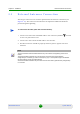
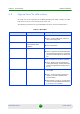
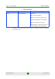
Table Of Contents
- BreezeMAX Extreme System Manual
- About This Manual
- Contents
- System Description
- 1.1 About WiMAX
- 1.2 WiMAX Network Architecture
- 1.3 BreezeMAX Extreme
- 1.4 Specifications
- Installation
- 2.1 BTS Installation
- 2.2 GPS Installation
- 2.3 Indoor Power Supply Installation
- 2.4 Cable Connections
- 2.5 External Antennas Connection
- Commissioning
- Operation and Administration
- 4.1 BreezeMAX Extreme System Management
- 4.2 The Monitor Program
- 4.3 IP Addresses Configuration
- 4.4 The Main Menu
- 4.5 BTS Menu
- 4.5.1 Show Summary
- 4.5.2 Show Properties
- 4.5.3 Configuration
- 4.5.4 Unit Control
- 4.5.5 Fault Management
- 4.5.6 Performance Counters
- 4.6 ASN-GW Menu
- 4.7 Sector Menu
- 4.8 BS Menu
- 4.9 Radio Channel Menu
- 4.10 Antenna Menu
- 4.11 GPS Menu
- 4.12 MS Menu
- 4.13 Parameters Summary
- Glossary
Chapter 2 - Installation Cable Connections
BreezeMAX Extreme 48 System Manual
the PoE PS to the backhauling equipment using a standard Ethernet cable.
Connect the PoE PS to the 110/220 VAC mains.
2.4.1.3 DC Power Cable Connection (not applicable if using PoE)
The power cable is supplied with a specially designed sealing gland that should
replace the existing gland provided with the BreezeMAX Extreme BTS.
Cables are available either open ended at the Power Supply side or with a crimped
D-Type connector.
1 Remove the existing gland from the 48V connection on the BTS.
2 Attach the DC power cable with the already assembled gland to the 48V
connection on the BTS.
3 Separate the sealing gland nut from the gland body.
4 Use the dedicated tool to fasten the gland to the BTS.
5 Use the dedicated tool to fasten the sealing gland's nut on the gland body.
6 Connect the other end of the power cable to the high power AC/DC power
supply.Use a standard power cable to connect to 48V DC power source.
NOTE
The combined lengths of the Ethernet cables should not exceed 100m.
To connect the power cable: