
User's Manual
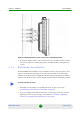
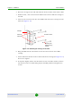
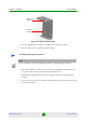
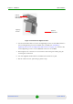
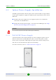
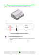
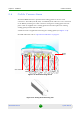
Table Of Contents
- BreezeMAX Extreme System Manual
- About This Manual
- Contents
- System Description
- 1.1 About WiMAX
- 1.2 WiMAX Network Architecture
- 1.3 BreezeMAX Extreme
- 1.4 Specifications
- Installation
- 2.1 BTS Installation
- 2.2 GPS Installation
- 2.3 Indoor Power Supply Installation
- 2.4 Cable Connections
- 2.5 External Antennas Connection
- Commissioning
- Operation and Administration
- 4.1 BreezeMAX Extreme System Management
- 4.2 The Monitor Program
- 4.3 IP Addresses Configuration
- 4.4 The Main Menu
- 4.5 BTS Menu
- 4.5.1 Show Summary
- 4.5.2 Show Properties
- 4.5.3 Configuration
- 4.5.4 Unit Control
- 4.5.5 Fault Management
- 4.5.6 Performance Counters
- 4.6 ASN-GW Menu
- 4.7 Sector Menu
- 4.8 BS Menu
- 4.9 Radio Channel Menu
- 4.10 Antenna Menu
- 4.11 GPS Menu
- 4.12 MS Menu
- 4.13 Parameters Summary
- Glossary
Chapter 2 - Installation Cable Connections
BreezeMAX Extreme 44 System Manual
2.4 Cable Connections
The BreezeMAX Extreme is provided with sealing glands on all the cable
connectors. The DATA/DC IN/OUT, and GPS IN/OUT cables are to be connected
to the BTS by inserting the cable connector through the sealing gland. The DC
power cable is supplied with a sealing gland that should replace the existing
sealing gland provided with the BTS.
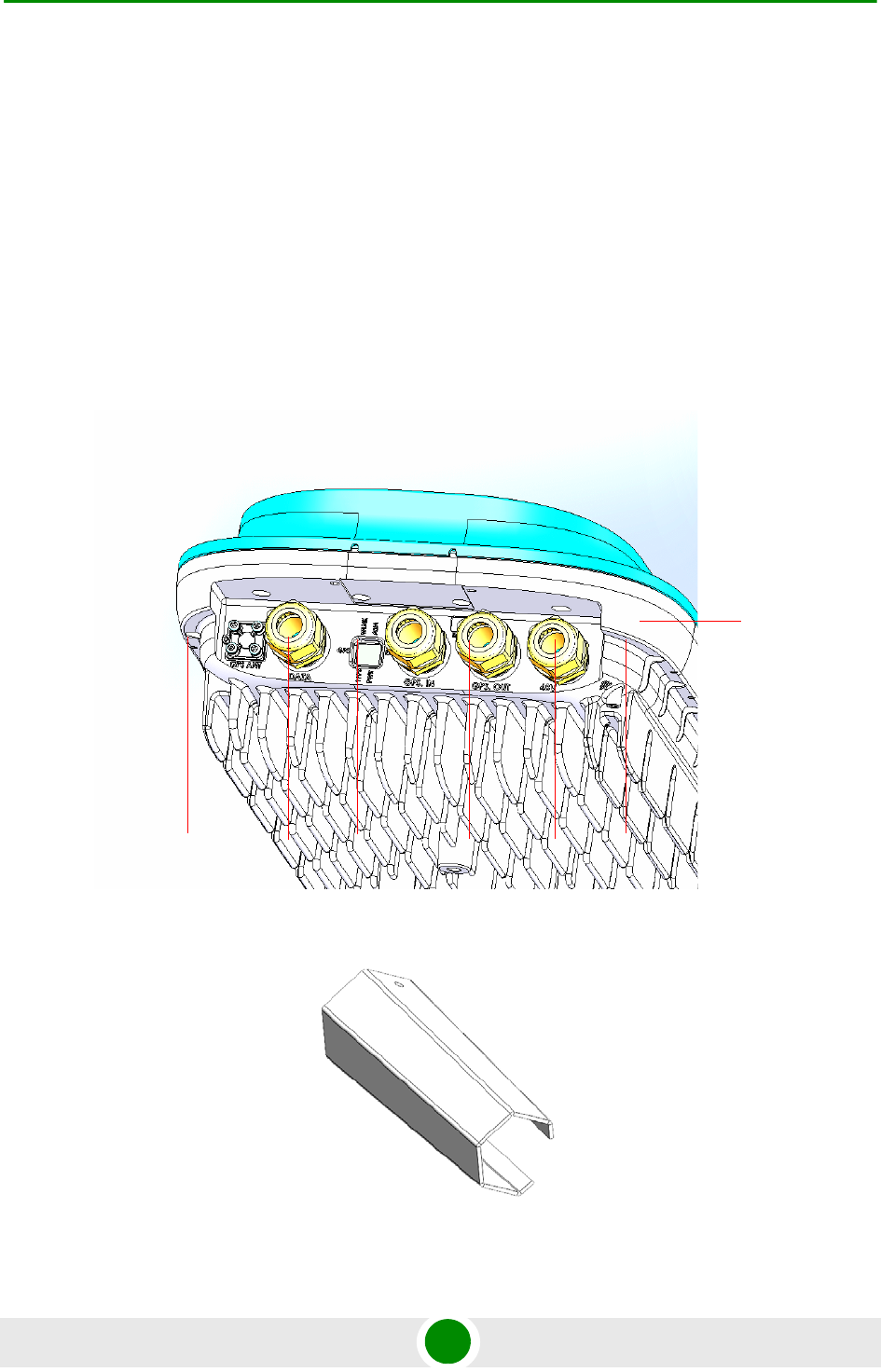
A dedicated tool is supplied for fastening the sealing glands (see Figure 2-16).
For LED indication refer to “Operation Verification” on page 54.
Figure 2-15: BTS with Sealing Glands
Figure 2-16: Sealing Gland Fastening Tool
Sealed LED
window
GPS Antenna
GPS OUT
Sealing
Gland
GPS IN
DATA DC
IN/OUT
48V
power