
User's Manual
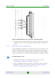
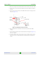
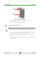
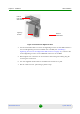
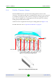
Table Of Contents
- BreezeMAX Extreme System Manual
- About This Manual
- Contents
- System Description
- 1.1 About WiMAX
- 1.2 WiMAX Network Architecture
- 1.3 BreezeMAX Extreme
- 1.4 Specifications
- Installation
- 2.1 BTS Installation
- 2.2 GPS Installation
- 2.3 Indoor Power Supply Installation
- 2.4 Cable Connections
- 2.5 External Antennas Connection
- Commissioning
- Operation and Administration
- 4.1 BreezeMAX Extreme System Management
- 4.2 The Monitor Program
- 4.3 IP Addresses Configuration
- 4.4 The Main Menu
- 4.5 BTS Menu
- 4.5.1 Show Summary
- 4.5.2 Show Properties
- 4.5.3 Configuration
- 4.5.4 Unit Control
- 4.5.5 Fault Management
- 4.5.6 Performance Counters
- 4.6 ASN-GW Menu
- 4.7 Sector Menu
- 4.8 BS Menu
- 4.9 Radio Channel Menu
- 4.10 Antenna Menu
- 4.11 GPS Menu
- 4.12 MS Menu
- 4.13 Parameters Summary
- Glossary
Chapter 2 - Installation Indoor Power Supply Installation
BreezeMAX Extreme 43 System Manual
2.3.2 High Power AC/DC Power Supply Unit
1 Place the Power Supply on a table/shelf or use 4 screws to mount the unit to
the wall.
2 For cable connection, refer to “Cable Connection” on page 46.
Figure 2-14: Indoor High Power AC/DC Power Supply Unit
To install the indoor high power supply unit:
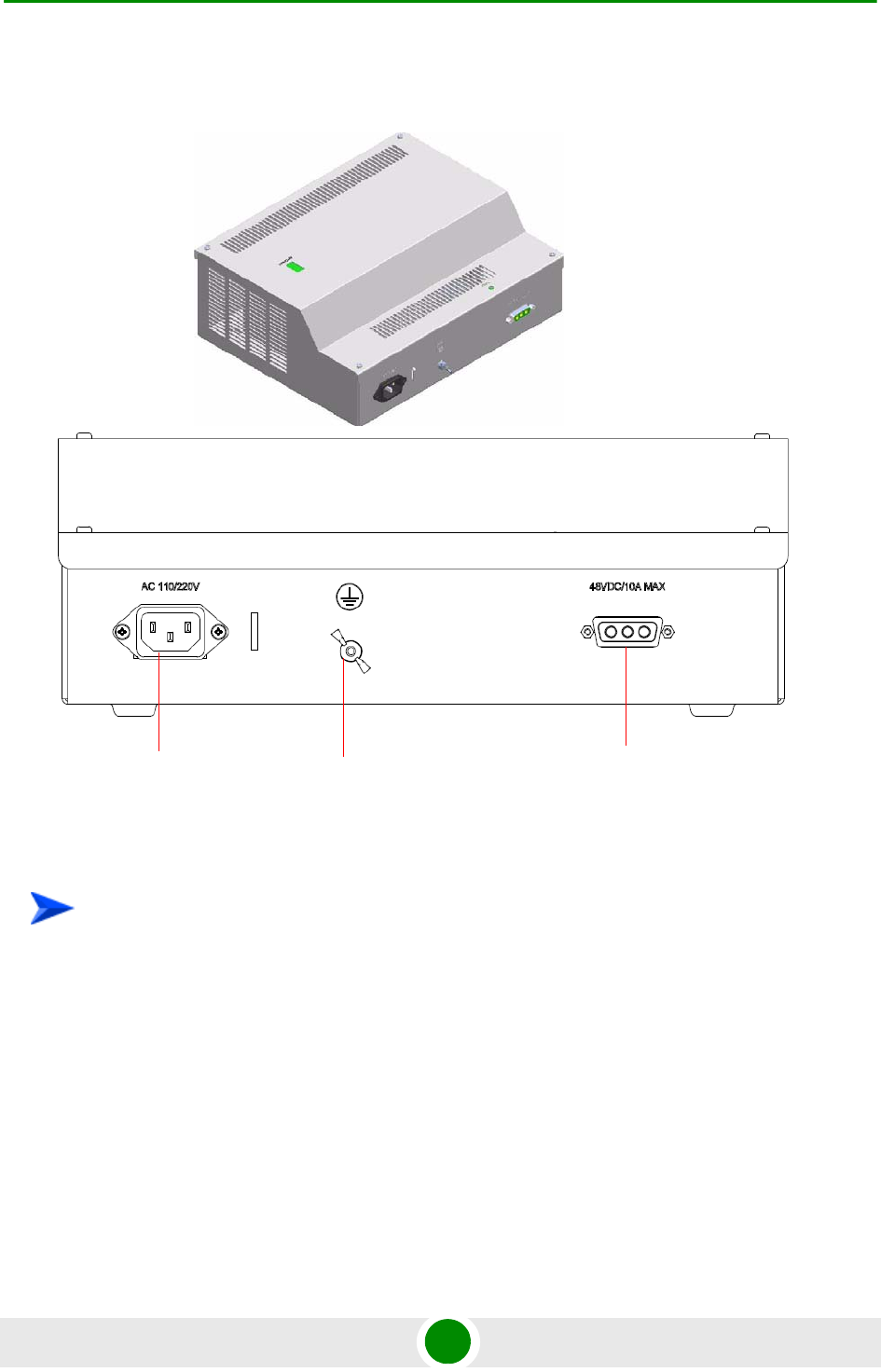
DC Power
connection
AC Power
connection
Grounding