
User's Manual
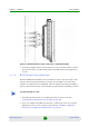
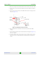
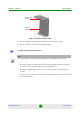
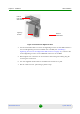
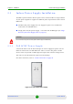
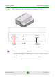
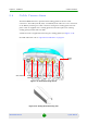
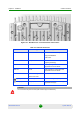
Table Of Contents
- BreezeMAX Extreme System Manual
- About This Manual
- Contents
- System Description
- 1.1 About WiMAX
- 1.2 WiMAX Network Architecture
- 1.3 BreezeMAX Extreme
- 1.4 Specifications
- Installation
- 2.1 BTS Installation
- 2.2 GPS Installation
- 2.3 Indoor Power Supply Installation
- 2.4 Cable Connections
- 2.5 External Antennas Connection
- Commissioning
- Operation and Administration
- 4.1 BreezeMAX Extreme System Management
- 4.2 The Monitor Program
- 4.3 IP Addresses Configuration
- 4.4 The Main Menu
- 4.5 BTS Menu
- 4.5.1 Show Summary
- 4.5.2 Show Properties
- 4.5.3 Configuration
- 4.5.4 Unit Control
- 4.5.5 Fault Management
- 4.5.6 Performance Counters
- 4.6 ASN-GW Menu
- 4.7 Sector Menu
- 4.8 BS Menu
- 4.9 Radio Channel Menu
- 4.10 Antenna Menu
- 4.11 GPS Menu
- 4.12 MS Menu
- 4.13 Parameters Summary
- Glossary
Chapter 2 - Installation GPS Installation
BreezeMAX Extreme 39 System Manual
High gain GPS Antenna
» High gain antenna
» 25m cable
» Pole mount bracket
» Two metal bands
» Carriage mounting bracket
» Two Lightning Arrestors with 0.5m cables, including screws, washers, and
spring washers (2 x UNC10-32)
2.2.3 Installing the GPS
1 Place the bracket on a flat surface and thread the GPS antenna through the
hole at the top of the bracket. Hand-tighten the fastening nut.
2 Assemble the lightning arrestor on the bracket, with the screws facing the
bracket. Connect one end of the 0.5 m cable to the lightning arrestor and the
other end to the GPS antenna.
3 Connect one end of the GPS 3m cable to the lightning arrestor, and the other
end to the GPS ANT connector on the BTS.
NOTE
The lightning arrestors supplied within the GPS kit are not included in the warranty cover provided
for the GPS unit.
Additional lightning arrestors can be ordered separately.
To install the basic GPS antenna: