
User's Manual
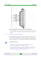
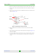
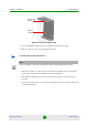
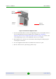
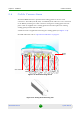
Table Of Contents
- BreezeMAX Extreme System Manual
- About This Manual
- Contents
- System Description
- 1.1 About WiMAX
- 1.2 WiMAX Network Architecture
- 1.3 BreezeMAX Extreme
- 1.4 Specifications
- Installation
- 2.1 BTS Installation
- 2.2 GPS Installation
- 2.3 Indoor Power Supply Installation
- 2.4 Cable Connections
- 2.5 External Antennas Connection
- Commissioning
- Operation and Administration
- 4.1 BreezeMAX Extreme System Management
- 4.2 The Monitor Program
- 4.3 IP Addresses Configuration
- 4.4 The Main Menu
- 4.5 BTS Menu
- 4.5.1 Show Summary
- 4.5.2 Show Properties
- 4.5.3 Configuration
- 4.5.4 Unit Control
- 4.5.5 Fault Management
- 4.5.6 Performance Counters
- 4.6 ASN-GW Menu
- 4.7 Sector Menu
- 4.8 BS Menu
- 4.9 Radio Channel Menu
- 4.10 Antenna Menu
- 4.11 GPS Menu
- 4.12 MS Menu
- 4.13 Parameters Summary
- Glossary
Chapter 2 - Installation BTS Installation
BreezeMAX Extreme 37 System Manual
3 Place the carriage on the wall and mark the exact location of the holes to drill.
4 Drill the holes, and use four metal dowels and screws to affix the carriage to
the wall.
5 Insert the tilt control screws into the middle-side hole of the carriage on both
sides (see Figure 2-10).
6 Hang the BTS with the tilt bracket on the tilt control screws of the BTS
carriage.
7 Attach and fasten all the screws at both sides of the carriage (see Figure 2-10).
Do not over tighten.
8 If required, slightly release the tilt bracket screws to enable rotation, and the
tilt control screws to enable tilting; Adjust the BTS position and tighten the
screws.
Figure 2-10: Mounting the Carriage on the Wall
Carriage
Till control screw
Holes for
wallmount
screws (to be
fastened using
dowels