
User's Manual

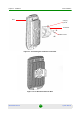
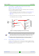
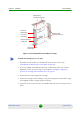
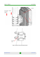
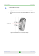
Table Of Contents
- BreezeMAX Extreme System Manual
- About This Manual
- Contents
- System Description
- 1.1 About WiMAX
- 1.2 WiMAX Network Architecture
- 1.3 BreezeMAX Extreme
- 1.4 Specifications
- Installation
- 2.1 BTS Installation
- 2.2 GPS Installation
- 2.3 Indoor Power Supply Installation
- 2.4 Cable Connections
- 2.5 External Antennas Connection
- Commissioning
- Operation and Administration
- 4.1 BreezeMAX Extreme System Management
- 4.2 The Monitor Program
- 4.3 IP Addresses Configuration
- 4.4 The Main Menu
- 4.5 BTS Menu
- 4.5.1 Show Summary
- 4.5.2 Show Properties
- 4.5.3 Configuration
- 4.5.4 Unit Control
- 4.5.5 Fault Management
- 4.5.6 Performance Counters
- 4.6 ASN-GW Menu
- 4.7 Sector Menu
- 4.8 BS Menu
- 4.9 Radio Channel Menu
- 4.10 Antenna Menu
- 4.11 GPS Menu
- 4.12 MS Menu
- 4.13 Parameters Summary
- Glossary
Chapter 2 - Installation BTS Installation
BreezeMAX Extreme 32 System Manual
1 Assemble the tilt bracket on the BTS and fasten its four screws (see
“Assembling the Tilt Bracket on the BTS” on page 29).
2 If you use a High-Gain GPS antenna with a cable longer than 3m, install a
lightning arrestor on the carriage as described in “Installing a Lightning
Arrestor for the High-Gain GPS Antenna” on page 31.
3 Thread the four rods through the carriage.
4 Attach the carriage and the clamps to the pole and tighten on both sides using
the supplied washers, spring washers and nuts.
5 Insert the tilt control screws into the middle-side hole of the carriage on both
sides.
Figure 2-4: BreezeMAX Extreme Pole Mount Carriage
To install the Carriage on a 1.5''-4'' pole:
Holes for pole
mounting rods (x4)
Holes for wall
mounting screws (x4)
Groove for
metal bands
Holes for fastening
screws (x4)
Tilt control
screws (x2)
Holes for lightning
arrestor (x4)