
User's Manual
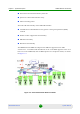
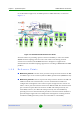
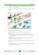
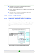
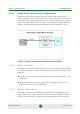
Table Of Contents
- BreezeMAX Extreme System Manual
- About This Manual
- Contents
- System Description
- 1.1 About WiMAX
- 1.2 WiMAX Network Architecture
- 1.3 BreezeMAX Extreme
- 1.4 Specifications
- Installation
- 2.1 BTS Installation
- 2.2 GPS Installation
- 2.3 Indoor Power Supply Installation
- 2.4 Cable Connections
- 2.5 External Antennas Connection
- Commissioning
- Operation and Administration
- 4.1 BreezeMAX Extreme System Management
- 4.2 The Monitor Program
- 4.3 IP Addresses Configuration
- 4.4 The Main Menu
- 4.5 BTS Menu
- 4.5.1 Show Summary
- 4.5.2 Show Properties
- 4.5.3 Configuration
- 4.5.4 Unit Control
- 4.5.5 Fault Management
- 4.5.6 Performance Counters
- 4.6 ASN-GW Menu
- 4.7 Sector Menu
- 4.8 BS Menu
- 4.9 Radio Channel Menu
- 4.10 Antenna Menu
- 4.11 GPS Menu
- 4.12 MS Menu
- 4.13 Parameters Summary
- Glossary
Chapter 1 - System Description BreezeMAX Extreme
BreezeMAX Extreme 13 System Manual
AlvariSTAR central management system allowing multiple elements
management and performance monitoring.
StarACS – Automatic Configuration Server for TR-069 based management and
monitoring of CPEs.
AlvariCRAFT element management system allowing a single element
management for BTS installation/maintenance.
1.3.3 System Configurations
In the current release the following BTS configurations are available:
1.3.3.1 Single Sector, Second Order Diversity Configurations
Single Sector Second Order Diversity (1DIV models) units include a BS connected
to two internal radios with either an integral dual-slant antenna or two RF
connections to external antenna(s). 1DIV model units support Single Sector
Single BS with Diversity operation mode providing a bandwidth of up to 10 MHz
per sector. A dual-slant antenna (internal or external) or two external antennas
support second order diversity with MIMO in the downlink and MRC in the
uplink.
Figure 1-6: Single Sector Single BS with Diversity Operation Mode