
User's Manual
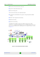
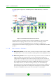
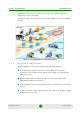
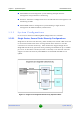
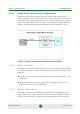
Table Of Contents
- BreezeMAX Extreme System Manual
- About This Manual
- Contents
- System Description
- 1.1 About WiMAX
- 1.2 WiMAX Network Architecture
- 1.3 BreezeMAX Extreme
- 1.4 Specifications
- Installation
- 2.1 BTS Installation
- 2.2 GPS Installation
- 2.3 Indoor Power Supply Installation
- 2.4 Cable Connections
- 2.5 External Antennas Connection
- Commissioning
- Operation and Administration
- 4.1 BreezeMAX Extreme System Management
- 4.2 The Monitor Program
- 4.3 IP Addresses Configuration
- 4.4 The Main Menu
- 4.5 BTS Menu
- 4.5.1 Show Summary
- 4.5.2 Show Properties
- 4.5.3 Configuration
- 4.5.4 Unit Control
- 4.5.5 Fault Management
- 4.5.6 Performance Counters
- 4.6 ASN-GW Menu
- 4.7 Sector Menu
- 4.8 BS Menu
- 4.9 Radio Channel Menu
- 4.10 Antenna Menu
- 4.11 GPS Menu
- 4.12 MS Menu
- 4.13 Parameters Summary
- Glossary
Chapter 1 - System Description BreezeMAX Extreme
BreezeMAX Extreme 12 System Manual
The BTS can simultaneously serve up to 40 CPEs, with optional upgrades to
support up to 150 or 250 CPEs.
The following figure describes the end-to-end BreezeMAX Extreme based WiMAX
network:
1.3.2 System Components
The BreezeMAX Extreme system consists of the following elements:
BreezeMAX Extreme Base Transceiver Station (BTS) and associated
accessories such as GPS antenna, indoor power supply and, (if applicable)
external antennas.
External ASN-GW for centralized architecture and optional Embedded
ASN-GW for distributed architecture.
Optional AAA server for central authentication, authorization and accounting
services.
Outdoor and indoor CPEs supporting VoIP, Data, Switching, Bridging, tagging
and marking functionality.
Figure 1-5: BreezeMAX Extreme System Architecture