
User's Manual
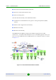
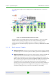
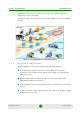
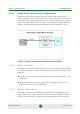
Table Of Contents
- BreezeMAX Extreme System Manual
- About This Manual
- Contents
- System Description
- 1.1 About WiMAX
- 1.2 WiMAX Network Architecture
- 1.3 BreezeMAX Extreme
- 1.4 Specifications
- Installation
- 2.1 BTS Installation
- 2.2 GPS Installation
- 2.3 Indoor Power Supply Installation
- 2.4 Cable Connections
- 2.5 External Antennas Connection
- Commissioning
- Operation and Administration
- 4.1 BreezeMAX Extreme System Management
- 4.2 The Monitor Program
- 4.3 IP Addresses Configuration
- 4.4 The Main Menu
- 4.5 BTS Menu
- 4.5.1 Show Summary
- 4.5.2 Show Properties
- 4.5.3 Configuration
- 4.5.4 Unit Control
- 4.5.5 Fault Management
- 4.5.6 Performance Counters
- 4.6 ASN-GW Menu
- 4.7 Sector Menu
- 4.8 BS Menu
- 4.9 Radio Channel Menu
- 4.10 Antenna Menu
- 4.11 GPS Menu
- 4.12 MS Menu
- 4.13 Parameters Summary
- Glossary

Chapter 1 - System Description WiMAX Network Architecture
BreezeMAX Extreme 10 System Manual
Reference point R3 consists of the set of control plane protocols between the
ASN and CSN to support AAA, policy enforcement and mobility management
capabilities. It also encompasses the bearer plane methods (e.g. tunneling) to
transfer user data between the ASN and CSN.
Reference point R4 consists of the set of control and bearer plane protocols
originating/terminating in various functional entities of an ASN that
coordinate MS mobility between ASNs and ASN-GWs. R4 is the only
interoperable reference point between similar or heterogeneous ASNs.
Reference point R5 consists of the set of control plane and bearer plane
protocols for internet working between the CSN operated by the home NSP and
that operated by a visited NSP.
Reference point R6 consists of the set of control and bearer plane protocols
for communication between the BS and ASN-GW. The bearer plane consists of
an intra-ASN data path between the BS and ASN gateway. The control plane
includes protocols for data path establishment, modification and release
control in accordance with the MS mobility events.
Reference point R8 consists of the set of control plane message flows and
optional bearer plane data flows between the base stations to ensure a fast
and seamless handover. The bearer plane consists of protocols that allow data
transfer between base stations involved in the handover of a certain MS.
It is important to note that all reference points are logical and do not necessarily
imply a physical or even direct connection. For instance, the R4 reference point
between ASN-GWs might be implemented across the NAP internal transport IP
network, in which case R4 traffic might traverse several routers from the source to
the destination ASN-GW.