
User's Manual
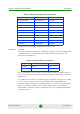
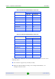
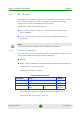
Table Of Contents
- BreezeMAX Extreme System Manual
- About This Manual
- Contents
- System Description
- 1.1 About WiMAX
- 1.2 WiMAX Network Architecture
- 1.3 BreezeMAX Extreme
- 1.4 Specifications
- Installation
- 2.1 BTS Installation
- 2.2 GPS Installation
- 2.3 Indoor Power Supply Installation
- 2.4 Cable Connections
- 2.5 External Antennas Connection
- Commissioning
- Operation and Administration
- 4.1 BreezeMAX Extreme System Management
- 4.2 The Monitor Program
- 4.3 IP Addresses Configuration
- 4.4 The Main Menu
- 4.5 BTS Menu
- 4.5.1 Show Summary
- 4.5.2 Show Properties
- 4.5.3 Configuration
- 4.5.4 Unit Control
- 4.5.5 Fault Management
- 4.5.6 Performance Counters
- 4.6 ASN-GW Menu
- 4.7 Sector Menu
- 4.8 BS Menu
- 4.9 Radio Channel Menu
- 4.10 Antenna Menu
- 4.11 GPS Menu
- 4.12 MS Menu
- 4.13 Parameters Summary
- Glossary

Chapter 4 - Operation and Administration BS Menu
BreezeMAX Extreme 135 System Manual
Tables 437 & 438 in the standard provide the series to use for each Preamble
Index according to FFT size.
For details on MAC parameters refer to “MAC” on page 139
PHY
Current Diversity Mode
Configured Diversity Mode
Current UL Thermal Noise level
Configured UL Thermal Noise level
Bandwidth (MHz): The BS Bandwidth depends on the configured Sector
Bandwidth and Operation Mode. For Single Sector Single BS (with or without
Diversity) Operation Modes the BS Bandwidth equals the Sector Bandwidth
(see “Bandwidth” on page 124).
For details on PHY parameters refer to “PHY” on page 140
Multi Rate
UL Minimum Sub-Channels
Current Uplink Multi Rate Support
Configured Uplink Multi Rate Support
Current Uplink Basic Rate
Configured Uplink Basic Rate
Current Uplink Fade Margin
Configured Uplink Fade Margin
Current Downlink Multi Rate Support
Configured Downlink Multi Rate Support
Current Downlink Basic Rate