
User Manual

Amplifier Kit
BreezeNET PRO.11 Series 0-1 User’s Guide
AMPLIFIER KIT
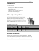
Each Amplifier Kit Includes:
• Bi-directional Amplifier, AMP2440-250 or AMP2440-500
• DC Power Injector
• 5ft. LMR-400 cable (N-male to N-female)
• 2 N-male to N-male adapters
• 110/220 VAC to 12VDC Power Supply, and power cord
• Stainless Steel U-Bolt and mounting bracket
• Vapor wrap coaxial connector sealing tape
• Installation Manual
Cable Length vs. Output Power
The AMP2440 is an amplifier designed for installation by professional
radio installers. Several key factors unique to the particular installation
determine the power level at the input of the amplifier. The most
important consideration is the cable loss in the transmission cable between
the radio and the pole mounted amp. It is important that the installer
understand these and other factors when computing the input power to the
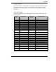
amplifier. The table below shows cable length and output power for both
the 250mW and 500mW models.
Power Output vs. Cable Length
AMP model Cable type Length Power in Power out
AMP2440-250 LMR-400 30 ft. 13.9dBm 24dBm/250mW*
AMP2440-250 LMR-400 50 ft. 12.5dBm 24dBm.250mW*
AMP2440-250 LMR-400 100 ft. 9dBm 24dBm/250mW
AMP2440-250 LMR-600 150 ft. 9dBm 24dBm/250mW
AMP2440-500 LMR-600 22 ft. 15dBm 27dBm/500mW
AMP2440-500 LMR-600 100 ft. 11.5dBm 26.5dBm/447mW
* higher output power is not possible because the output is limited.
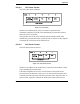
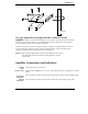
Installation and Mounting
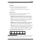
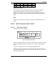
The amplifier can be mast mounted using the steel U-bolt included with the unit. The amplifier
should be installed with the connectors facing downward. After placing the assembly on the mast,
use an open-end wrench to carefully tighten the nuts. Take care not to over-tighten the nuts or you
may inadvertently strip the threads. See the diagram below for proper assembly.