
User Manual

Accessory Installation
BreezeNET PRO.11 Series 6-3 User’s Guide
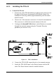
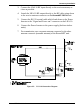
6. Connect the RF cable leading from the Power Inserter to the
transmit antenna on the BreezeNET PRO.11 unit.
7. Plug the power cable leading from the Power Inserter into any
available 110/220V outlet. The power supply must be installed
indoors.
Note: Installations exceeding regulations set by local authorities expose the
installer and the user to potential legal and financial liabilities.
8. For reception, use a separate antenna connected to the other
antenna connector of the BreezeNET unit.
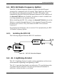
6.2. LNA 10 Low Noise Receive Amplifier
The LNA 10 is a high-performance, low-noise preamplifier designed to
enhance fringe area reception and provide additional gain on the receive
antenna. Its exceptionally small size and light weight enables it to be
directly mounted on the antenna by means of the female RF IN connector.
Power is obtained through an RG-59 coaxial cable connected to the power
supply. The LNA 10 is internally protected against lightning and voltage
surge protection.
The Power Supply (PS) and Power Inserter are supplied with the LNA 10.
The RG-59 coaxial cable with F-type connector is not supplied and must be
purchased separately.
For technical specifications, refer to Specifications for LNA 10 Low Noise
Receive Amplifier in the appendices.
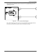
6.2.1. Installing the LNA 10
Before installing the LNA 10, the following steps must be taken:
1. Choose one of the antenna connectors to be used for reception. This
connector is called the receive antenna of the unit. The other
connector is called the transmit antenna of the unit.
2. Configure the BreezeNET PRO.11 unit via the Monitor to transmit
through the transmit antenna only using the Transmit Diversity
parameter (see section 3.4.3). This prevents transmission from
going through the LNA 10.