
User's Manual
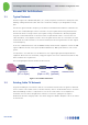
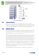
Table Of Contents
- 1 Introduction
- 2 The Concept
- 3 BreezeCELL Architecture
- 4 BreezeCELL Network Elements
- 5 Frequency Allocations
- 6 MIMO Support
- 7 Monitoring & Control
- 8 Installation Requirements and Procedures
- 9 Headend Equipment Installation
- 9.1 Connector Information
- 9.2 Rack Installation
- 9.3 Connecting the BreezeCELL Equipment
- 9.4 Connecting the Monitoring System
- 9.5 Connecting External Alarms
- 9.6 Connecting the Base Stations
- 9.7 UDC Configuration
- 9.8 Pilot Master/Slave Configuration
- 9.9 Measurements
- 9.10 Connecting to the Coax TV Networks
- 9.11 Measurements
- 9.12 Localized Testing Port
- 9.13 Determining BTS Output Power VS. Remote Unit Output Power
- 10 Coax Network Amplifier Installation (if applicable)
- 11 Remote Unit Installation
- 12 Preparing for Remote Unit Installation
- 13 Normal Operations
- 14 Acceptance Testing

In-building Cellular Solution for Commercial Buildings UDC Software Configuration Tool
BreezeCELL
2
3 BreezeCELL Architecture
3.1 Typical Network
A wireless signal source (BTS/Node B/, Micro, Pico, Femto, Repeater) is installed in a central point in the
building. Cabling infrastructure (fiber and coax) is installed according to a pre-designed RF coverage
plan.
The wireless signal is shifted in frequency to the Alvarion intermediate band and then combined in the
RF level. The combined RF signal is then converted to an optical signal which is being transmitted via
the fiber link. At the coverage area the optical signal is being converted back to RF and propagated
along the coaxial network down to the remote units. If required and in order to overcome the coax
cable attenuation, a wire amplifier is used to boost the signal. Remote units are connected to the cable
and transmit via a built-in antenna (or an external antenna) the wireless signals indoors at their original
licensed frequency.
In the case of TDD transmissions such as WiMAX and LTE, the BreezeCELL equipment converts the TDD
signal to FDD at both ends of the system (Headend and Remote). TDD synchronization is run over the
system.
It is important to note that there is no modification to the original signal generated by the Wireless
equipment. BreezeCELL is an active DAS, carrying the signal to the remote small antenna (Remote unit)
where it radiates in its original form.
The following diagram illustrates the BreezeCELL network:
Figure 1: BreezeCELL Architecture
3.2 Existing Cable TV Network
A typical in building TV coax network is built as a tree and branch architecture. TV signals are delivered
from a common source (which can be a terrestrial antenna, CATV or satellite dish/receiver) to TV outlets
within the building. In order to compensate for losses in the coaxial cables a set of amplifiers are
installed at various locations throughout the network to increase the signal gain. The signal is
distributed to branches using taps and to the outlets using power dividers. Amplifiers can also be found
in the branches.
BTS/Node B
UDC/OCD
(RF <> Optic)
OCN
(Optic <> RF)
Amplifier
(optional)
Remote Units
Fiber
Coax