
User's Manual
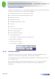
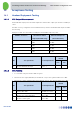
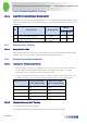
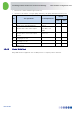
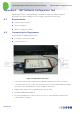
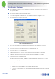
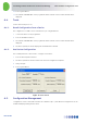
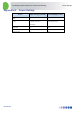
Table Of Contents
- 1 Introduction
- 2 The Concept
- 3 BreezeCELL Architecture
- 4 BreezeCELL Network Elements
- 5 Frequency Allocations
- 6 MIMO Support
- 7 Monitoring & Control
- 8 Installation Requirements and Procedures
- 9 Headend Equipment Installation
- 9.1 Connector Information
- 9.2 Rack Installation
- 9.3 Connecting the BreezeCELL Equipment
- 9.4 Connecting the Monitoring System
- 9.5 Connecting External Alarms
- 9.6 Connecting the Base Stations
- 9.7 UDC Configuration
- 9.8 Pilot Master/Slave Configuration
- 9.9 Measurements
- 9.10 Connecting to the Coax TV Networks
- 9.11 Measurements
- 9.12 Localized Testing Port
- 9.13 Determining BTS Output Power VS. Remote Unit Output Power
- 10 Coax Network Amplifier Installation (if applicable)
- 11 Remote Unit Installation
- 12 Preparing for Remote Unit Installation
- 13 Normal Operations
- 14 Acceptance Testing

In-building Cellular Solution for Commercial Buildings UDC Software Configuration Tool
BreezeCELL
37
1. Measure the cellular downlink signal (walk test)
2. Generate a call and test: coverage quality (walk test), call quality and uplink transmit power
No. Test Operations Test Requirement
Results
Pass Fail
1 Verify remote unit LED illuminate Green
2 Measure wall outlet cellular signal * -20 dBm to -50
dBm
3 Measure direct remote unit output
power*
See 3.2.1
4 Outgoing voice call
5 Incoming voce call
6 Data session
14.4.3 Global Walk Test
Using dedicated test equipment such as TEMS perform a complete premises walk test.