
User's Manual
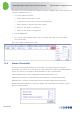
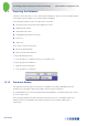
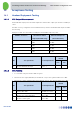
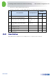
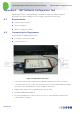
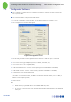
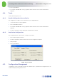
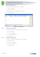
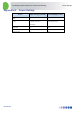
Table Of Contents
- 1 Introduction
- 2 The Concept
- 3 BreezeCELL Architecture
- 4 BreezeCELL Network Elements
- 5 Frequency Allocations
- 6 MIMO Support
- 7 Monitoring & Control
- 8 Installation Requirements and Procedures
- 9 Headend Equipment Installation
- 9.1 Connector Information
- 9.2 Rack Installation
- 9.3 Connecting the BreezeCELL Equipment
- 9.4 Connecting the Monitoring System
- 9.5 Connecting External Alarms
- 9.6 Connecting the Base Stations
- 9.7 UDC Configuration
- 9.8 Pilot Master/Slave Configuration
- 9.9 Measurements
- 9.10 Connecting to the Coax TV Networks
- 9.11 Measurements
- 9.12 Localized Testing Port
- 9.13 Determining BTS Output Power VS. Remote Unit Output Power
- 10 Coax Network Amplifier Installation (if applicable)
- 11 Remote Unit Installation
- 12 Preparing for Remote Unit Installation
- 13 Normal Operations
- 14 Acceptance Testing

In-building Cellular Solution for Commercial Buildings UDC Software Configuration Tool
BreezeCELL
36
14.2 Coax Network Amplifier Testing
14.2.1 Amplifier Downlink Signal Measurement
Measure the cellular downlink signal at the UL IN port of the amplifier (The amplified downlink signal).
Verify existence of the pilot signal at 962 MHz and of the cellular signal. Both signals should be at a 0 ±
3 dBm level.
No. Test Operations Test Requirement
Results
Pass Fail
1 Measure Pilot signal (962 MHz) 0 ± 3 dBm
2 Measure Cellular signal 0 ± 3 dBm
14.3 Remote Unit Testing
14.3.1 Remote Unit LEDs
Verify that the LED on the remote unit’s front illuminate. After power up the LED should turn orange
and after a few seconds turn green. In Normal operations LED should be green
14.4 Remote Unit Measurements
14.4.1 Testing the First Remote Units
1. Measure signal levels at the coax cable connection between the wall outlet and the remote unit.
The pilot and the cellular signals should be visible at levels between -20 dBm to – 50 dBm
(dependant of the coax length in this specific network branch)
2. In case a remote unit with external RF outputs is available, measure that the output power is 0 or
10 dBm (according to remote unit type) and the RF output is at the correct cellular frequency
Number of carriers Remote unit output
power (0 dBm model)
Remote unit output
power (10 dBm model)
1 0 dB 10 dB
2 3 dB 13 dB
4 6 dB 16 dB
8 9 dB 19 dB
14.4.2 Standard Remote Unit Testing
For all remote units perform the following:
Using dedicated cellular test equipment (Handset with test mode or specialized h/w)