
User's Manual
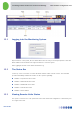
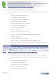
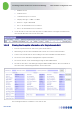
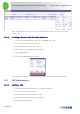
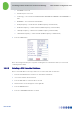
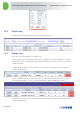
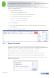
Table Of Contents
- 1 Introduction
- 2 The Concept
- 3 BreezeCELL Architecture
- 4 BreezeCELL Network Elements
- 5 Frequency Allocations
- 6 MIMO Support
- 7 Monitoring & Control
- 8 Installation Requirements and Procedures
- 9 Headend Equipment Installation
- 9.1 Connector Information
- 9.2 Rack Installation
- 9.3 Connecting the BreezeCELL Equipment
- 9.4 Connecting the Monitoring System
- 9.5 Connecting External Alarms
- 9.6 Connecting the Base Stations
- 9.7 UDC Configuration
- 9.8 Pilot Master/Slave Configuration
- 9.9 Measurements
- 9.10 Connecting to the Coax TV Networks
- 9.11 Measurements
- 9.12 Localized Testing Port
- 9.13 Determining BTS Output Power VS. Remote Unit Output Power
- 10 Coax Network Amplifier Installation (if applicable)
- 11 Remote Unit Installation
- 12 Preparing for Remote Unit Installation
- 13 Normal Operations
- 14 Acceptance Testing

In-building Cellular Solution for Commercial Buildings UDC Software Configuration Tool
BreezeCELL
32
13.6 Events Log
All actions performed in the system are documented in the Event Log
13.7 Alarms Log
The main screen after logging in, is the Alarm Log.
A list of all active alarms is displayed on the screen. According to the amount and details of concurrent
alarms, the operators can analyze the alarm to determine whether the cause is a specific remote unit or
a network problem.
A single remote unit alarm will cause the dry contacts output #0 to change position (from Normally
Closed to Normally Open)
In case of a multiple remote units failure that have crossed the multiple alarm threshold (see section
3.8) a message will appear on the top of the alarm window to indicate Multiple units failure.
A Multiple remote unit alarm will cause the dry contacts output #1 to change position (from Normally
Closed to Normally Open)