
User's Manual
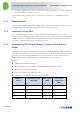
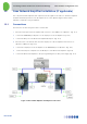
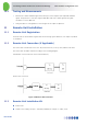
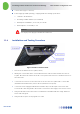
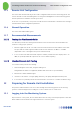
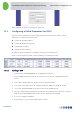
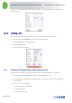
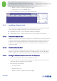
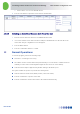
Table Of Contents
- 1 Introduction
- 2 The Concept
- 3 BreezeCELL Architecture
- 4 BreezeCELL Network Elements
- 5 Frequency Allocations
- 6 MIMO Support
- 7 Monitoring & Control
- 8 Installation Requirements and Procedures
- 9 Headend Equipment Installation
- 9.1 Connector Information
- 9.2 Rack Installation
- 9.3 Connecting the BreezeCELL Equipment
- 9.4 Connecting the Monitoring System
- 9.5 Connecting External Alarms
- 9.6 Connecting the Base Stations
- 9.7 UDC Configuration
- 9.8 Pilot Master/Slave Configuration
- 9.9 Measurements
- 9.10 Connecting to the Coax TV Networks
- 9.11 Measurements
- 9.12 Localized Testing Port
- 9.13 Determining BTS Output Power VS. Remote Unit Output Power
- 10 Coax Network Amplifier Installation (if applicable)
- 11 Remote Unit Installation
- 12 Preparing for Remote Unit Installation
- 13 Normal Operations
- 14 Acceptance Testing

In-building Cellular Solution for Commercial Buildings UDC Software Configuration Tool
BreezeCELL
17
10.2 Testing and Measurements
1. Measure the cellular downlink signal at the UL IN port of the amplifier (The amplified downlink
signal). Verify existence of the pilot signal at 962 MHz and of the cellular signal. Both signals
should be at a 0 ± 3 dBm level
2. Verify that there is no degradation to the TV signal at the output of diplexer 2.
11 Remote Unit Installation
11.1 Remote Unit Registration
Each new remote unit should be registered in the monitoring system data base (See chapter 10) PRIOR
to installation.
11.2 Remote Unit Connection (if Applicable)
The remote unit is installed in series to the TV, between the TV (or Set Top box) and the wall outlet.
The remote unit should be installed according to the following diagram:
Standard TV connection (before remote unit installation):
Remote unit connection:
Figure 14: Remote Unit Connection
11.3 Remote Unit Installation Kit
Remote unit
AC/DC Power Supply: AC Input - 100-240V, 50/60Hz; DC Output – 5.7 VDC, 3.5 A