
User's Manual
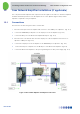
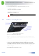
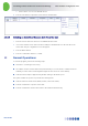
Table Of Contents
- 1 Introduction
- 2 The Concept
- 3 BreezeCELL Architecture
- 4 BreezeCELL Network Elements
- 5 Frequency Allocations
- 6 MIMO Support
- 7 Monitoring & Control
- 8 Installation Requirements and Procedures
- 9 Headend Equipment Installation
- 9.1 Connector Information
- 9.2 Rack Installation
- 9.3 Connecting the BreezeCELL Equipment
- 9.4 Connecting the Monitoring System
- 9.5 Connecting External Alarms
- 9.6 Connecting the Base Stations
- 9.7 UDC Configuration
- 9.8 Pilot Master/Slave Configuration
- 9.9 Measurements
- 9.10 Connecting to the Coax TV Networks
- 9.11 Measurements
- 9.12 Localized Testing Port
- 9.13 Determining BTS Output Power VS. Remote Unit Output Power
- 10 Coax Network Amplifier Installation (if applicable)
- 11 Remote Unit Installation
- 12 Preparing for Remote Unit Installation
- 13 Normal Operations
- 14 Acceptance Testing

In-building Cellular Solution for Commercial Buildings UDC Software Configuration Tool
BreezeCELL
16
10 Coax Network Amplifier Installation (if applicable)
The coax plant includes amplifiers that compensate the TV signal for the cable loss. A wireless amplifier
should be installed in parallel to each TV amplifier. A set of two diplexers (bypass filters) and an
amplifier is required for every TV amplifier.
10.1 Connections
All connection are done using an F-male to F-male cable
1. Disconnect the input of the TV amplifier and connect it to the CABLE port of diplexer 1. (Fig. 15-1)
2. Connect the AMPLIFIER port diplexer 1 to the input port of the TV amplifier. (Fig. 15-2)
3. Connect the RPT port to the BreezeCELL amplifier DL IN port. (Fig. 15-3)
4. Disconnect the coax network cable from the output port of the TV amplifier and connect it to
diplexer 2 CABLE port. (Fig. 15-4)
5. Connect the output port of the TV amplifier to the AMPLIFIER port of diplexer 2. (Fig. 15-5)
6. Connect the RPT port of diplexer 2 to the UL IN port of the BreezeCELL amplifier. (Fig 15-6)
7. Connect the BreezeCELL amplifier to the power grid using the 7.5 VDC power supply. (Fig. 15-7)
Figure 13: BreezeCELL Amplifier and Diplexer Connection