
User's Manual
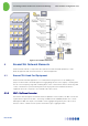
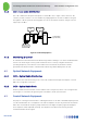
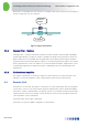
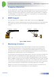
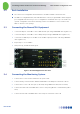
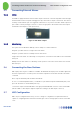
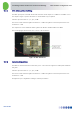
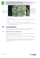
Table Of Contents
- 1 Introduction
- 2 The Concept
- 3 BreezeCELL Architecture
- 4 BreezeCELL Network Elements
- 5 Frequency Allocations
- 6 MIMO Support
- 7 Monitoring & Control
- 8 Installation Requirements and Procedures
- 9 Headend Equipment Installation
- 9.1 Connector Information
- 9.2 Rack Installation
- 9.3 Connecting the BreezeCELL Equipment
- 9.4 Connecting the Monitoring System
- 9.5 Connecting External Alarms
- 9.6 Connecting the Base Stations
- 9.7 UDC Configuration
- 9.8 Pilot Master/Slave Configuration
- 9.9 Measurements
- 9.10 Connecting to the Coax TV Networks
- 9.11 Measurements
- 9.12 Localized Testing Port
- 9.13 Determining BTS Output Power VS. Remote Unit Output Power
- 10 Coax Network Amplifier Installation (if applicable)
- 11 Remote Unit Installation
- 12 Preparing for Remote Unit Installation
- 13 Normal Operations
- 14 Acceptance Testing

In-building Cellular Solution for Commercial Buildings UDC Software Configuration Tool
BreezeCELL
13
Figure 11: Gain Configuration
If configuration is required:
1. Measure the signal at the UDC DL out port and configure the Pilot signal (962 MHz) to be 0 ± 1
dBm.
2. Measure the cellular downlink signal at the UDC DL out port and adjust it to be 0 ± 1 dBm.
3. Measure the signal at the UDC UL in port and adjust the uplink cellular signal so there is a 0 ± 5 dB
end-to-end Gain (Remote Unit to UDC).
9.7.3 Frequency Configuration
UDC frequency configuration is required in the event the UDC is not pre-configured with the correct
operating frequencies. Using the configuration software is described in appendix A.
9.8 Pilot Master/Slave Configuration
When working with multiple UDCs only one pilot signal should be generated. Therefore one UDC
should be configured as Master and the rest as Slaves.
Note: The power to the UDC and CCD units should be disconnected before performing the following
procedure.
Locate the Master/Slave jumper on the further left corner of the main UDC circuit board. There are
three pins. Place the jumper (J9) on the left and middle pins for Master. Place the jumper (J9) on the
right and middle pins for Slave.