
User's Manual
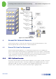
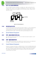
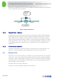
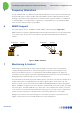
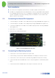
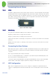
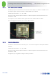
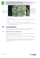
Table Of Contents
- 1 Introduction
- 2 The Concept
- 3 BreezeCELL Architecture
- 4 BreezeCELL Network Elements
- 5 Frequency Allocations
- 6 MIMO Support
- 7 Monitoring & Control
- 8 Installation Requirements and Procedures
- 9 Headend Equipment Installation
- 9.1 Connector Information
- 9.2 Rack Installation
- 9.3 Connecting the BreezeCELL Equipment
- 9.4 Connecting the Monitoring System
- 9.5 Connecting External Alarms
- 9.6 Connecting the Base Stations
- 9.7 UDC Configuration
- 9.8 Pilot Master/Slave Configuration
- 9.9 Measurements
- 9.10 Connecting to the Coax TV Networks
- 9.11 Measurements
- 9.12 Localized Testing Port
- 9.13 Determining BTS Output Power VS. Remote Unit Output Power
- 10 Coax Network Amplifier Installation (if applicable)
- 11 Remote Unit Installation
- 12 Preparing for Remote Unit Installation
- 13 Normal Operations
- 14 Acceptance Testing

In-building Cellular Solution for Commercial Buildings UDC Software Configuration Tool
BreezeCELL
11
9.5 Connecting External Alarms
9.5.1 UDCs
Each UDC is equipped with an external alarm output at the back of the unit. Any UDC failure will light
the Alarm LED on the front panel and trigger the dry contact whose output is at the back. The alarm is
normally closed and will open once triggered or when there is no power to the UDC. Alarm output is at
pins 2 and 3 of the 9 pin D-type connector. Connect an appropriate cable between the alarm output
and the BTS alarm input (or other input source).
Figure 9: UDC Alarm Output
9.5.2 Monitoring
The system uses an Advantech USB dry contacts adaptor for alarm indications.
Relay #0 – provides alarm for a single remote unit failure
Relay #1 – provides alarm for a multiple remote units failure
Single remote unit alarm: For a Normally closed operation connect NC0 and COM0 to the relevant BTS
alarm port
Multiple remote units alarm: For a Normally closed operation connect NC1 and COM1 to the relevant
BTS alarm port
9.6 Connecting the Base Stations
UDC input power range is +10 dBm to +33 dBm. The BTS/Node B output power should be adjusted to
meet this requirement. In case BTS power exceeds the requirement an external attenuator should be
connected
Note: Only the downlink path should be attenuated!
In case of a combined up/down links, it is advisable to split between uplink and downlink paths, and
place the attenuator on the downlink path only.
Connect the output of the BTS/Node B to the appropriate BTS/Node B connector in the relevant UDC
(An N-to-SMA or other adaptor might be required according to the BTS output connector).
9.7 UDC Configuration
UDCs are pre-configured at the factory. In case a change of configuration is required the units are
capable of configuring the BTS attenuation and the gain control. Setting requires removal of the UDC
cover.