
User's Manual
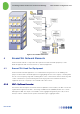
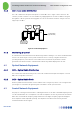
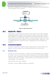
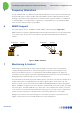
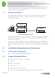
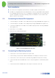
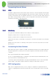
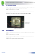
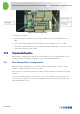
Table Of Contents
- 1 Introduction
- 2 The Concept
- 3 BreezeCELL Architecture
- 4 BreezeCELL Network Elements
- 5 Frequency Allocations
- 6 MIMO Support
- 7 Monitoring & Control
- 8 Installation Requirements and Procedures
- 9 Headend Equipment Installation
- 9.1 Connector Information
- 9.2 Rack Installation
- 9.3 Connecting the BreezeCELL Equipment
- 9.4 Connecting the Monitoring System
- 9.5 Connecting External Alarms
- 9.6 Connecting the Base Stations
- 9.7 UDC Configuration
- 9.8 Pilot Master/Slave Configuration
- 9.9 Measurements
- 9.10 Connecting to the Coax TV Networks
- 9.11 Measurements
- 9.12 Localized Testing Port
- 9.13 Determining BTS Output Power VS. Remote Unit Output Power
- 10 Coax Network Amplifier Installation (if applicable)
- 11 Remote Unit Installation
- 12 Preparing for Remote Unit Installation
- 13 Normal Operations
- 14 Acceptance Testing

In-building Cellular Solution for Commercial Buildings UDC Software Configuration Tool
BreezeCELL
10
9.2 Rack Installation
The CCD is a non-configurable unit and therefore should be installed as the bottom unit.
The UDCs are configurable units (Gain and Attenuation controls). In general UDCs will be shipped
pre-configured from the factory. In case a configuration is needed the box’s top cover needs to be
opened. Configuration can be done externally, however it is advisable to leave room above the
UDCs to allow for cover opening.
9.3 Connecting the BreezeCELL Equipment
1. Connect the DL port of the UDC to the CCD Down Link port using a SMA/SMA cable. (Figure 11-1)
2. Connect the UL port of the UDC to the CCD Up Link port using a SMA/SMA cable. (Figure 11-2)
3. Connect the 10 MHz in port of the UDC to the 10 MHz output port in the CCD using a BNC/BNC
cable. (Figure 11-3)
4. Repeat steps 1 – 3 for all UDCs
5. After power up, all LEDs should be green.
Figure 8: Headend Equipment Connections
9.4 Connecting the Monitoring System
1. Connect the PC to the monitor and both to the power outlet
2. Connect the Dry contacts interface Advantech USB-4761 to the USB port at the back of the PC
3. Connect the PC to the CCD serial port (on the back) using a DB9 serial cable (male to female)
4. Connect the female side of the DB9 cable to the PC serial port (light blue colored with the symbol
IOIOI)
5. Connect the male side of the DB9 cable to the serial port on the back of the CCD