
User's Manual
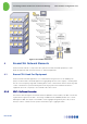
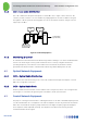
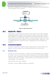
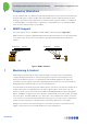
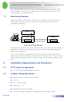
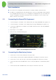
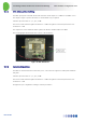
Table Of Contents
- 1 Introduction
- 2 The Concept
- 3 BreezeCELL Architecture
- 4 BreezeCELL Network Elements
- 5 Frequency Allocations
- 6 MIMO Support
- 7 Monitoring & Control
- 8 Installation Requirements and Procedures
- 9 Headend Equipment Installation
- 9.1 Connector Information
- 9.2 Rack Installation
- 9.3 Connecting the BreezeCELL Equipment
- 9.4 Connecting the Monitoring System
- 9.5 Connecting External Alarms
- 9.6 Connecting the Base Stations
- 9.7 UDC Configuration
- 9.8 Pilot Master/Slave Configuration
- 9.9 Measurements
- 9.10 Connecting to the Coax TV Networks
- 9.11 Measurements
- 9.12 Localized Testing Port
- 9.13 Determining BTS Output Power VS. Remote Unit Output Power
- 10 Coax Network Amplifier Installation (if applicable)
- 11 Remote Unit Installation
- 12 Preparing for Remote Unit Installation
- 13 Normal Operations
- 14 Acceptance Testing

In-building Cellular Solution for Commercial Buildings UDC Software Configuration Tool
BreezeCELL
7
5 Frequency Allocations
The up and down links of 75 MHz can be split and shared between several operators and technologies.
A typical GSM operator requires 10 MHz and a typical UMTS operator 5 MHZ. Frequency allocation
planning is done based on the required services and technologies. A typical example is a combination
of GSM and UMTS on a single network. Together they occupy 15MHz out of the available 75 MHz.
Other operators and technologies can be added
6 MIMO Support
The system supports SISO or 2x2 MIMO (A and B). MIMO is supported using a single cable.
MIMO channels are frequency duplexed within the BreezeCELL band and sent across the infrastructure
to the remote units. At the remote each channel is separated and transmitted from a dedicated
antenna.
Figure 6: MIMO Utilization
7 Monitoring & Control
Monitoring provides the network operator with the ability to remotely monitor and if required
configure the BreezeCELL Remotes. The Monitoring System comprises monitoring agents in the
Remotes and a web based server co-located with the cable headend equipment. The agents are
responsible for monitoring the status and configuring the Remotes while the server is responsible for
displaying the data and interfacing to the user in a friendly manner.
The traffic between the monitoring system and the agents is carried over a proprietary communication
modem channel that is established between the Remote agents and the server via the CCD. This
channel is carried over the CATV network using dedicated bandwidth within the Alvarion band (960
MHz to 1155MHz). The physical layer of the channel is implemented by a two-way modem, an integral
part of the agent. The MAC (Media Access Control) layer of the communication channel controls the
access scheme over the shared CATV medium. A proprietary protocol is used over this communication
channel in order to minimize the CPU performance and memory requirements of the agents.
During normal operation, the monitoring system receives failure messages from the Remotes and
triggers a visual alarm on the screen with identification of the faulty Remote.
BS
MIMO Remote
Ch1
Ch2
Downstream
Ch1
Ch2
Upstream
Ch1
Ch2
Downstream
Ch1
Ch2
Upstream