
User's Manual
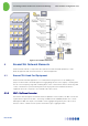
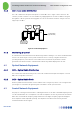
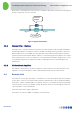
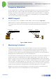
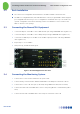
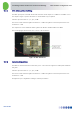
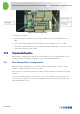
Table Of Contents
- 1 Introduction
- 2 The Concept
- 3 BreezeCELL Architecture
- 4 BreezeCELL Network Elements
- 5 Frequency Allocations
- 6 MIMO Support
- 7 Monitoring & Control
- 8 Installation Requirements and Procedures
- 9 Headend Equipment Installation
- 9.1 Connector Information
- 9.2 Rack Installation
- 9.3 Connecting the BreezeCELL Equipment
- 9.4 Connecting the Monitoring System
- 9.5 Connecting External Alarms
- 9.6 Connecting the Base Stations
- 9.7 UDC Configuration
- 9.8 Pilot Master/Slave Configuration
- 9.9 Measurements
- 9.10 Connecting to the Coax TV Networks
- 9.11 Measurements
- 9.12 Localized Testing Port
- 9.13 Determining BTS Output Power VS. Remote Unit Output Power
- 10 Coax Network Amplifier Installation (if applicable)
- 11 Remote Unit Installation
- 12 Preparing for Remote Unit Installation
- 13 Normal Operations
- 14 Acceptance Testing

In-building Cellular Solution for Commercial Buildings UDC Software Configuration Tool
BreezeCELL
5
4.1.2 CCD – Coax Cable Distribution
The CCD combines the RF inputs and outputs of several UDCs into a single coaxial connection. The
CCD also provides a reference clock for all UDCs by supplying them an accurate 10 MHz clock signal.
Through the CCD the system monitoring signals are sent to the network elements. A single CCD can
support up-to 8 UDCs.
960÷ 1155
MHz
CCD
Coaxial Cable
(Up and Down)
UDC
10 MHz
Cell
Microcell or
Repeater
Native
RF
Figure 4: Head End Equipment
4.1.3 Monitoring & Control
A communication link exists between the Monitoring software residing on a PC at the headend and the
remotes. The monitoring & control systems enables the user to remotely configure the Remotes
operating frequencies, turn a Remote on/off and monitor various Remote parameters. Alarms
generated at the Remotes will be communicated to Monitoring and be displayed for the user.
4.2 Optical Network Equipment
4.2.1 OCD – Optical Cable Distribution
The OCD has the same functionality of the CCD. OCD combines the RF inputs and outputs of several
UDCs into a single fiber connection.
4.2.2 OCN – Optical Cable Node
A fiber is pulled in between the BTS location and the main coverage area, where coax is being laid. The
optical signal is converted to RF signal using the OCN which is an RF optic transceiver.
4.3 Coaxial Network Equipment
The purpose of the bypass infrastructure is enabling the transfer of the 960 -1155 MHZ frequency band
over the standard cable TV Coax amplifiers. The cable TV amplifiers are the only element in the network
which does not handle this frequency range and therefore the higher frequency signal should bypass
those amplifiers and be amplified separately. The amplifiers are bi-directional and carry both the
forward and return wireless signals.