
User's Manual Part 2

BreezeCOMPACT System Manual
Chapter 4 - Operation and AdministrationBS Menu
Chapter 4 - Operation and Administration BS Menu
108
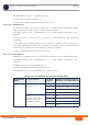
* First Zone Scheme is being determined by the FFR mode. Reuse 3 (FFR mode = ffrDlMap) is applicable
only for BS bandwidth of 10 MHz.
For First Zone Maximum Size the values are:
If First Zone Minimum Size is set to No Limitations, the value range for Maximum Size is the same as
for Minimum Size.
Else, the value range is No Limitations or First Zone Minimum Size+2N, up to a maximum of Y as
defined below.
The value of Y (which is actually the number of slots available for DL data) that sets the upper limit for
the Minimum and Maximum Size parameters depends on the Maximum Cell Radius and Total Uplink
Duration parameters, using the following formula:
Y=A-3*(Total Uplink Duration)-(Extra TTG),
where A=46 for BW of 5 or 10 MHz, and 32 for BW of 7 MHz.
5 MHz Full Loading
(FFR mode = none)
6N/A
4 No Limitation or 8+2N
2 No Limitation or 6+2N
1 No Limitation or 4+2N
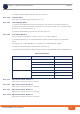
Table 4-2: Calculating the Upper Limit Value (Y) for Minimum and Maximum Size
BS Bandwidth
(MHz)
Maximum Cell
Radius
Total Uplink
Duration (slots)
Extra TTG
(symbols)
Upper Limit (Y)
5/10 1, 2, 4, 8 4 0 34
6028
1, 2, 4, 8, 15, 23 5 1 30
7124
15, 23, 30 4 2 32
6226
30 5 3 28
7322
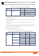
Table 4-1: First Zone Minimum Size Recommended Value Range
BS Bandwidth
(MHz)
First Zone Scheme* Basic Map
Repetition
Minimum Size (symbols) (up to a
maximum of Y as defined below)