
User's Manual Part 2


BreezeCOMPACT System Manual
Chapter 2 - BreezeCOMPACT InstallationConnecting the BreezeCOMPACT Cables
Chapter 2 - BreezeCOMPACT Installation Connecting the BreezeCOMPACT Cables
64
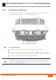
2.7.8 Connecting to Antennas
Four N-type connectors are used for the optional external antenna connection (see Figure 2-31). The
connectors must have an impedance of 50 Ohm and lightning protected.
1 Connect one end of the coaxial RF cable to the of the RF cable to the antenna ports.
2 Connect the other end to the connector port (marked ANT1 to ANT4) located on the rear panel of
the unit. Use a straight port configuration (antenna port 1 to ANT1 port on BTS, port 2 to ANT2, etc.)
3 Seal the RF connectors properly to protect against rain and moisture.
Figure 2-31: Antenna Connections
To connect the RF cable:
INFORMATION
The recommended minimum distance between any two antennas in neighboring sectors is 0.5 m.
The minimum distance between any two antennas in the same sector (space diversity configuration) is
1.3 m, that is 10 lambda (
λ), where λ=C/Frequency (Hz). C is the speed of light in centimeters per
second which is equal to 29,979,245,800.