
User's Manual Part 2

BreezeCOMPACT System Manual
Chapter 2 - BreezeCOMPACT InstallationConnecting the BreezeCOMPACT Cables
Chapter 2 - BreezeCOMPACT Installation Connecting the BreezeCOMPACT Cables
60
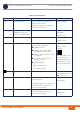
9 Add shield to the drain wire.
10 Attach suitable terminal rings to the side that connects to the power source.
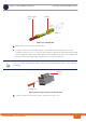
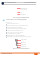
11 When connecting to a circuit breaker, see Figure 2-27 below for the location on the cable. Use a 10A
breaker.
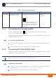
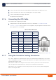
For connecting cables to connectors with sealing glands, refer to “Using the Connector Sealing
Accessories” on page 61.
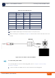
1 Connect the cable to the PWR connector on the unit and close the sealing gland.
Table 2-5: Power Cable Pin-out
Connector pin Signal Name 4 pin cable 6 pin cable
1 48V_RTN Black Black
2 48V_RTN Green Green
4 +48V Red Red
5 +48V White White
Orange (not connected)
Blue (not connected)
6 Shield Shield Shield
3 Not Connected
Figure 2-27: Power Cable for BreezeCOMPACT
To connect the power cable: