
User's Manual Part 2

BreezeCOMPACT System Manual
Chapter 2 - BreezeCOMPACT InstallationConnecting the BreezeCOMPACT Cables
Chapter 2 - BreezeCOMPACT Installation Connecting the BreezeCOMPACT Cables
59
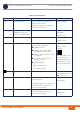
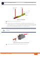
6 Repeat steps 3 and 4 for each of the five wires.
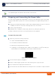
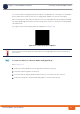
7 To insert a contact into the housing, align the contact with the desired cavity at the rear of the
housing as shown in Figure 2-26. In all rows the locking lance must be facing away from the housing
latch to engage the contact in the cavity. Push the contact straight into the cavity until an audible click
is heard. Give the lead a light tug to confirm that the contact is locked in place.
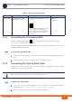
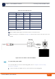
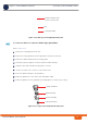
8 Connect the wires to the mini-fit connector as follows (see Figure 2-27):
Figure 2-25: Crimped Wire
INFORMATION
Figure 2-26 reflects the direction in which the pins are connected. Make sure that you connect the pins
accordingly.
Figure 2-26: Inserting a Contact into the Housing
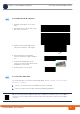
Ter mi na lWire external
jacket
Housing
latch
Locking lance