
User's Manual Part 2

BreezeCOMPACT System Manual
Chapter 2 - BreezeCOMPACT InstallationConnecting the BreezeCOMPACT Cables
Chapter 2 - BreezeCOMPACT Installation Connecting the BreezeCOMPACT Cables
57
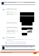
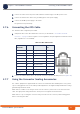
For connecting cables to connectors with sealing glands, refer to “Using the Connector Sealing
Accessories” on page 61.
1 Connect one end of the cable to the DAT3 connection on the BTS.
2 Connect the other end of the data cable the backhauling equipment.
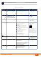
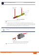
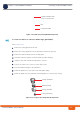
To assemble the RJ-45 connector:
1 Thread the RJ-45 plastic cover on the
cable.
2 Reveal 5cm of outer sleeve, then reveal
4cm of the inner sleeve.
3 Release all wires and arrange them in
order, then cut them to 1cm lengths.
4 Insert the wires into the shielded
connector and press it using a standard
tool
5 Solder the shield drain wire to the
connector as in the picture). Note the Pin
assignment for each cable.
6 Push the plastic cover into place.
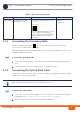
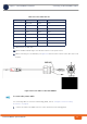
To connect the data cable:
CAUTION
When connecting any data equipment that does not support PoE (switch, hub, PC) to the DAT 3
connector, use only a 4-wire cable. Note that a DC Power hazard sticker appears near the DAT 3
connector.