
User's Manual Part 2

BreezeCOMPACT System Manual
Chapter 2 - BreezeCOMPACT InstallationConnecting the BreezeCOMPACT Cables
Chapter 2 - BreezeCOMPACT Installation Connecting the BreezeCOMPACT Cables
55
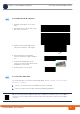
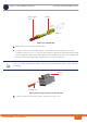
2.7.2 Connecting the Grounding Cable
The two Grounding screws (marked ) are located on the connectors panel of the unit (see
Figure 2-22). Use 10 AWG cable for grounding.
When grounding the unit, use the GND (ground) screws on the unit as grounding points, and connect
an additional cable between them.
1 Connect one end of a grounding cable to the ground terminal and firmly tighten the grounding
screw.
2 Connect the opposite end of the grounding cable to a ground connection.
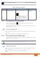
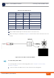
2.7.3 Connecting the Optical Data Cable
The OM3 optical cable is supplied ready for connection, including a sealing gland. The cable is available
from Alvarion in 50m and 100m lengths.
1 Connect one end of the cable to the DAT 1 connector on the BTS (for connecting cables using the
sealing glands refer to “Using the Connector Sealing Accessories” on page 61).
2 Connect the other end of the cable to the management equipment.
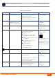
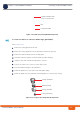
ANT1 - ANT4 4 x N-Type jack, 50 Ohm,
lightning protected
Connection to external antenna(s). See
Section 2.7.8.
CAUTION
To prevent lightning damage to the unit,
connect only DC ground lightning
protected antennas with short LMR-400
cables (0.5m/1m) to these ANT1-4
connectors.
LMR-400
Length:
≤1m
To connect the grounding cable:
NOTE!
DAT2 must be disabled in order for connectivity with DAT1 to function.
To connect the optical cable:
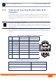
Table 2-2: BTS Connectors (Continued)
Connection Connector Type Functionality Cable