
User's Manual
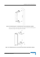

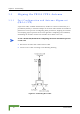
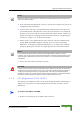
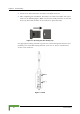
Table Of Contents
- About This Manual
- Contents
- Figures
- Tables
- Chapter 1 - Products Description
- 1.1 BreezeMAX CPEs
- 1.2 Introducing BreezeMAX PRO-S CPE
- 1.3 Introducing BreezeMAX Si CPE
- 1.4 Voice and Networking Gateways
- 1.5 PRO-S CPE Specifications
- 1.6 Si CPE Specifications
- Chapter 2 - Installation
- 2.1 Installing the ODU of the PRO-S CPE
- 2.2 Installing the IDU-1D Indoor Unit of the PRO-S CPE
- 2.3 Installing the Si CPE
- 2.4 Installing the 3.5 GHz Detached Antenna
- 2.5 Installing the 2.3/2.5 GHz Detached Antenna
- Chapter 3 - Commissioning
- Chapter 4 - Operation
- 4.1 The SU Installer Monitor Program
- 4.2 Using the Monitor Program
- 4.3 The Main Menu
- 4.4 Unit Control Menu
- 4.5 Registration Parameters Menu
- 4.6 BST/AU ID Parameters Menu
- 4.7 ˘Radio Parameters Menu
- 4.8 Multirate and ATPC Parameters Menu
- 4.9 Performance Monitoring Menu
- 4.10 FDD Parameters (3.x GHz units only)
- 4.11 ˘SU Parameters Summary
- Appendix A - The Web Configuration Server
- Appendix B - Troubleshooting
- Glossary

68 Commissioning
Chapter 3 - Commissioning
2 Connect the cable attached to the SAU to the SAU connector.
3 After completing the installation, disconnect the cable and replace the cap as
shown in the following figure. Make sure that the small protrusion on the side
of the cap fits inside the hole on the connector's protective body:
Use appropriate sealing material to protect the connection against moisture and
humidity. Use removable sealing material, such as a tar seal, to enable future
access to the connector.
Figure 3-2: Inserting the SAU Sealing Cap
Figure 3-3: SAU