
User's Manual
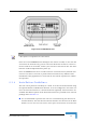
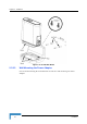
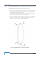
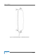
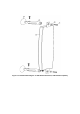
Table Of Contents
- BreezeMAX CPEs Product Manual
- About This Manual
- Contents
- Figures
- Tables
- Chapter 1 - Products Description
- Chapter 2 - Installation
- 2.1 Installing the ODU of the PRO-S CPE
- 2.2 Installing the IDU-1D Indoor Unit of the PRO-S CPE
- 2.3 Installing the Si CPE
- 2.4 Installing the 3.5 GHz Detached Antenna
- 2.5 Installing the 2.3/2.5 GHz Detached Antenna
- Chapter 3 - Commissioning
- Chapter 4 - Operation
- 4.1 The SU Installer Monitor Program
- 4.2 Using the Monitor Program
- 4.3 The Main Menu
- 4.4 Unit Control Menu
- 4.5 Registration Parameters Menu
- 4.6 BST/AU ID Parameters Menu
- 4.7 ˘Radio Parameters Menu
- 4.8 Performance Monitoring Menu
- 4.9 Multirate and ATPC Parameters Menu
- 4.10 ˘SU Parameters Summary
- Appendix A - The Web Configuration Server
- Appendix B - Troubleshooting
- Glossary

Installing the Si CPE
BreezeMAX CPEs Product Manual 43
4 Configure the basic parameters as described in Section 3.3.1.
5 Align the antenna as described in Section 3.5.
6 For E model units: Connect the 10/100 Base-T ETHERNET connector to the
data equipment. The cable connection should be a crossed Ethernet if
connecting to a hub/switch and a straight cable if connecting directly to a PC
Network Interface Card (NIC).
Verify proper operation of the Ethernet link. The Ethernet Integrity green LED
should be on and the Ethernet Activity yellow LED should blink when there is
Ethernet traffic. To verify data connectivity from the end-user's PC or from a
portable PC connected to the unit, ping a known device in the network, or try
connecting to the Internet.
For U model units: Use a USB cable to connect the USB connector on the unit
to the USB connector of the data equipment.
2.3.5.2 Wall Mounting the Si CPE
The wall mounting kit for the Si CPE includes a bracket, 2 screws, and 2 plastic
anchors. Refer to Figure 2-14.
1 If anchors are needed (wall-board, plaster board, etc.), drill two holes for the
anchors using a 6 mm drill bit and insert anchors. The distance between the
two holes should be 86 mm. Use the drilling template supplied with the Si
CPE.
2 Fasten the two screws provided with the kit directly to the anchors.
3 Use the two hangers on the rear to hang the mounting bracket on the two
screws. Make sure the bracket is stable.
4 Insert one side of the Si CPE's base diagonally under the
designated rail.
5 Gently apply pressure on the opposite side of the Si CPE,
until a clicking sound is heard and the two bracket studs
are locked onto the Si CPE's base.
To dismount the Si CPE, gently push the two bracket studs in
the direction of the wall and lift the CPE diagonally. Pull the CPE until free from
the rail.