
User's Manual
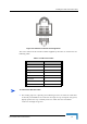
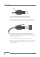
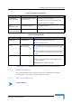
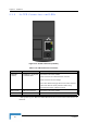
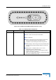
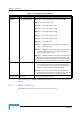
Table Of Contents
- BreezeMAX CPEs Product Manual
- About This Manual
- Contents
- Figures
- Tables
- Chapter 1 - Products Description
- Chapter 2 - Installation
- 2.1 Installing the ODU of the PRO-S CPE
- 2.2 Installing the IDU-1D Indoor Unit of the PRO-S CPE
- 2.3 Installing the Si CPE
- 2.4 Installing the 3.5 GHz Detached Antenna
- 2.5 Installing the 2.3/2.5 GHz Detached Antenna
- Chapter 3 - Commissioning
- Chapter 4 - Operation
- 4.1 The SU Installer Monitor Program
- 4.2 Using the Monitor Program
- 4.3 The Main Menu
- 4.4 Unit Control Menu
- 4.5 Registration Parameters Menu
- 4.6 BST/AU ID Parameters Menu
- 4.7 ˘Radio Parameters Menu
- 4.8 Performance Monitoring Menu
- 4.9 Multirate and ATPC Parameters Menu
- 4.10 ˘SU Parameters Summary
- Appendix A - The Web Configuration Server
- Appendix B - Troubleshooting
- Glossary

32 Installation
Chapter 2 - Installation
2 Connect the Ethernet cable to the IDU COM RJ-45 connector.
3 Put the sealing cap back in its place. Make sure that the small protrusion on
the side of the cap fits inside the hole on the connector's protective body.
4 Use appropriate sealing material to protect the connection against moisture
and humidity. Use removable sealing material, such as a tar seal, to enable
future access to the connector.
5 Route the cable to the location selected for the indoor equipment.
6 Assemble an RJ-45 connector with a protective cover on the indoor end of the
IDU-ODU cable. Refer to the pin assignment and color codes in standard
cables described above.
Figure 2-7: Inserting the IDU COM Cable into the Sealing Cap
Figure 2-8: Connecting the IDU COM connector and inserting the Sealing Cap