
User's Manual
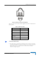
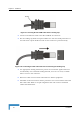
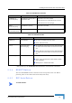
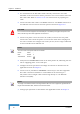
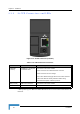
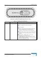
Table Of Contents
- BreezeMAX CPEs Product Manual
- About This Manual
- Contents
- Figures
- Tables
- Chapter 1 - Products Description
- Chapter 2 - Installation
- 2.1 Installing the ODU of the PRO-S CPE
- 2.2 Installing the IDU-1D Indoor Unit of the PRO-S CPE
- 2.3 Installing the Si CPE
- 2.4 Installing the 3.5 GHz Detached Antenna
- 2.5 Installing the 2.3/2.5 GHz Detached Antenna
- Chapter 3 - Commissioning
- Chapter 4 - Operation
- 4.1 The SU Installer Monitor Program
- 4.2 Using the Monitor Program
- 4.3 The Main Menu
- 4.4 Unit Control Menu
- 4.5 Registration Parameters Menu
- 4.6 BST/AU ID Parameters Menu
- 4.7 ˘Radio Parameters Menu
- 4.8 Performance Monitoring Menu
- 4.9 Multirate and ATPC Parameters Menu
- 4.10 ˘SU Parameters Summary
- Appendix A - The Web Configuration Server
- Appendix B - Troubleshooting
- Glossary

36 Installation
Chapter 2 - Installation
1 It is assumed that the IDU-ODU cable is already connected to the ODU.
Assemble an RJ-45 connector with a protective cover on the indoor end of the
IDU-ODU cable. Refer to Section 2.1.6.3 for instructions on preparing the
cable.
2 Connect the IDU-ODU cable to the RADIO connector. The RADIO connector in
the CPE-IDU-1D is located on the front panel as shown in Figure 2-9.
3 Connect the power cord to the unit's AC socket, located on the rear panel.
Connect the other end of the power cord to the AC mains after verifying that
the unit is rated for the voltage in the country of use; the AC range is indicated
on the back side of the CPE-IDU-1D.
4 Verify that the POWER LED located on the front panel is lit, indicating that the
unit is supplying power to the radio port.
5 Configure the basic parameters and align the antenna as described in the
applicable sections of Chapter 3.
6 Connect the 10/100 Base-T ETHERNET connector(s) to the data equipment.
The cable connection should be a crossed Ethernet if connecting to a
hub/switch and a straight cable if connecting directly to a PC Network
Interface Card (NIC).
7 Verify proper operation as described in the applicable section of Chapter 3.
CAUTION
Do not connect the data equipment to the RADIO port. The RADIO port supplies DC power to the
ODU, and this may harm other equipment connected to it.
NOTE
The color codes of the power cable are as follows:
Brown Phase ~
Blue Neutral 0
Yellow/Green Ground
NOTE
The length of the Ethernet cable connecting CPE-IDU-1D to the user's equipment, together with the
length of the IDU-ODU cable, should not exceed 100 meters.