
User's Manual
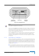
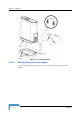
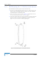
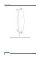
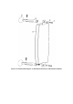
Table Of Contents
- BreezeMAX CPEs Product Manual
- About This Manual
- Contents
- Figures
- Tables
- Chapter 1 - Products Description
- Chapter 2 - Installation
- 2.1 Installing the ODU of the PRO-S CPE
- 2.2 Installing the IDU-1D Indoor Unit of the PRO-S CPE
- 2.3 Installing the Si CPE
- 2.4 Installing the 3.5 GHz Detached Antenna
- 2.5 Installing the 2.3/2.5 GHz Detached Antenna
- Chapter 3 - Commissioning
- Chapter 4 - Operation
- 4.1 The SU Installer Monitor Program
- 4.2 Using the Monitor Program
- 4.3 The Main Menu
- 4.4 Unit Control Menu
- 4.5 Registration Parameters Menu
- 4.6 BST/AU ID Parameters Menu
- 4.7 ˘Radio Parameters Menu
- 4.8 Performance Monitoring Menu
- 4.9 Multirate and ATPC Parameters Menu
- 4.10 ˘SU Parameters Summary
- Appendix A - The Web Configuration Server
- Appendix B - Troubleshooting
- Glossary

42 Installation
Chapter 2 - Installation
unit. Do not place any object between the selected antenna and the window
towards which the antenna is directed.
When a detached antenna is used, install it on a window or on a wall
according to specific conditions of the location. The antenna should be facing
the required direction. Use only the RF cable supplied with the antenna (if
needed, use a longer Ethernet cable).
Avoid metal obstacles such as metal window frames or metal film anti-glare
windows in the transmission path.
Position the unit (or the detached antenna) away from electrical equipment,
including the data equipment, monitor etc., metal furniture, and moving metal
objects such as metal fans or doors.
2.3.5 Installing the Si CPE
2.3.5.1 Connecting the Si CPE
1 Connect the Power Adapter DC cable to the POWER jack. Connect the AC
power cord to the Power Adapter. Connect the other end of the power cord to
the AC mains.
2 Verify that the orange Status LED located on the unit's top panel illuminates,
indicating that the power supply to the unit is OK and the unit is not yet
connected to a Base Station (the LED will change to green when the unit is
connected to a Base Station).
3 If a detached antenna is used, remove the cap on the unit's top panel to expose
the RF connector and connect to it the RF cable supplied with the antenna.
Install the antenna using the instructions provided in Section 2.4 on page 42,
and connect to it the other end of the RF cable. To tighten the SMA connectors,
use only the torque key supplied with the antenna.
To install the Si CPE:
NOTE
The color codes of the power cable are as follows:
Brown
Phase ~
Blue Neutral 0
Yellow/Green Ground